Ford Mustang (1999-2004) Service Manual: Parking, Rear and License Lamps
Refer to Wiring Diagrams Cell 92 , Exterior for schematic and connector information.
Special Tool(s)
 |
73 III Automotive Meter or equivalent 105-R0057 |
Inspection and Verification
1. Verify the customer concern by operating the parking lamps.
2. Visually inspect for the following obvious signs of mechanical and electrical damage.
Visual Inspection Chart
| Mechanical |
Electrical |
|
|
3. If the concern is not visually evident, determine the symptom and proceed to Symptom Chart.
Symptom Chart
| Condition | Possible Sources | Action |
|
|
|
|
|
|
|
|
|
Pinpoint Tests
PINPOINT TEST L: THE PARKING, REAR OR LICENSE LAMPS ARE INOPERATIVE
| Test Step | Result / Action to Take |
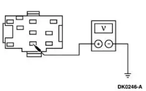
| L1 CHECK THE VOLTAGE TO THE HEADLAMP SWITCH | Yes GO to L2 . No REPAIR the circuit. TEST the system for normal operation. |
|
|
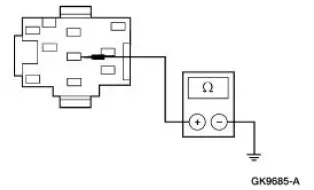
| L2 CHECK CIRCUIT 14 (BN) FOR OPEN | Yes INSTALL a new headlamp switch; REFER to Lamp Switch-Headlamp . TEST the system for normal operation. No REPAIR the circuit. TEST the system for normal operation. |
|
PINPOINT TEST M: ONE OR MORE PARKING, REAR OR LICENSE LAMP(S) IS INOPERATIVE
| Test Step | Result / Action to Take |
| M1 CHECK THE VOLTAGE TO THE INOPERATIVE LAMP(S) | Yes REPAIR Circuit 1205 (BK) for an open. TEST the system for normal operation. No REPAIR the circuit. TEST the system for normal operation |
|
PINPOINT TEST N: THE PARKING, REAR OR LICENSE LAMPS ARE ON CONTINUOUSLY
| Test Step | Result / Action to Take |
| N1 CHECK THE HEADLAMP SWITCH | Yes REPAIR Circuit 14 (BN) for a short to battery. TEST the system for normal operation. No INSTALL a new headlamp switch; REFER to Lamp Switch-Headlamp . TEST the system for normal operation |
|
 Turn Signal and Hazard Lamps
Refer to Wiring Diagrams Cell 90 , Turn/Stop/Hazard Lamps for schematic
and connector information.
Special Tool(s)
73 III Automotive Meter
105-R0057 or equivalent
Inspection and Ver ...
 Fog Lamps
Refer to Wiring Diagrams Cell 86 , Fog Lamps for schematic and connector
information.
Special Tool(s)
73 III Automotive Meter or
equivalent
105-R0057
Principles of Operation
The f ...
Other materials:
Refrigerant System Tests
Special Tool(s)
R-134a Manifold Gauge Set
176-R032A or equivalent
1. Connect the R-134a Manifold Gauge Set. For additional information, refer
to Manifold Gauge
Set Connection in this section.
2. Adjust the climate controls for maximum cooling ...
Gauges And Warning Devices
Refer to Wiring Diagrams Cell 59 , Generic Electronic Module for
schematic and connector
information.
Refer to Wiring Diagrams Cell 60 , Instrument Cluster for schematic and
connector information.
Refer to Wiring Diagrams Cell 66 , Warning Chime ...
General information
Make sure you review your device’s manual before using it with SYNC.
Support
The SYNC support team is available to help you with any questions you
cannot answer on your own.
Monday-Saturday, 8:30am-9:00pm EST.
Sunday, 10:30am-7:30pm EST.
In the United St ...
