Ford Mustang (1999-2004) Service Manual: Turn Signal and Hazard Lamps
Refer to Wiring Diagrams Cell 90 , Turn/Stop/Hazard Lamps for schematic and connector information.
Special Tool(s)
 |
73 III Automotive Meter 105-R0057 or equivalent |
Inspection and Verification
1. Verify the customer concern.
2. Visually inspect for the following obvious signs of mechanical and electrical damage.
Visual Inspection Chart
| Mechanical |
Electrical |
|
|
3. If an obvious cause for an observed or reported concern is found, correct the cause (if possible) before proceeding to the next step.
4. If the cause is not visually evident, verify the symptom and refer to the Symptom Chart.
Symptom Chart
| Condition | Possible Sources | Action |
|
|
|
|
|
|
|
|
|
|
|
|
|
|
|
Pinpoint Tests
PINPOINT TEST J: THE TURN SIGNAL LAMPS ARE NEVER ON
| Test Step | Result / Action to Take |
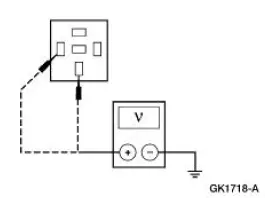
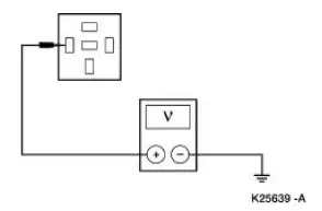
| J1 CHECK THE VOLTAGE TO THE ELECTRONIC FLASHER | Yes GO to J2 . No REPAIR the circuit in question. TEST the system for normal operation. |
|
|
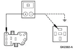
| J2 CHECK CIRCUIT 44 (LB) | Yes GO to J3 . No REPAIR the circuit. TEST the system for normal operation. |
|
|
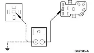
| J3 CHECK THE CONTINUITY OF THE MULTIFUNCTION SWITCH | Yes INSTALL a new electronic flasher. TEST the system for normal operation. No INSTALL a new multifunction switch. REFER to Section. TEST the system for normal operation. |
|
PINPOINT TEST K: THE HAZARD FLASHER LAMPS ARE NEVER ON
| Test Step | Result / Action to Take |
| K1 CHECK THE VOLTAGE TO THE ELECTRONIC FLASHER | Yes GO to K2 . No REPAIR the circuit. TEST the system for normal operation. |
|
|
| K2 CHECK CIRCUIT 385 (WH/RD) | Yes GO to K3 . No REPAIR the circuit. TEST the system for normal operation. |
|
|
| K3 CHECK THE CONTINUITY OF THE MULTIFUNCTION SWITCH | Yes INSTALL a new electronic flasher. TEST the system for normal operation. No INSTALL a new multifunction switch; REFER to Section. TEST the system for normal operation. |
|
 Stoplamps
Refer to Wiring Diagrams Cell 90 , Turn/Stop/Hazard Lamps for
schematic and connector information.
Special Tool(s)
73III Automotive Meter or
equivalent
105-R0057
Inspection and Ve ...
 Parking, Rear and License Lamps
Refer to Wiring Diagrams Cell 92 , Exterior for schematic and connector
information.
Special Tool(s)
73 III Automotive Meter or
equivalent
105-R0057
Inspection and Verification
1 ...
Other materials:
Anti-theft system
The active anti-theft system is designed to warn you in the event of
unauthorized vehicle entry and is also designed to help prevent
unwanted towing of the vehicle.
You can choose what is monitored by arming the system in different
ways.
Partial Monitor Mode
...
Installation
All vehicles
1. NOTE: If the valve cover is not secured within four minutes, the sealant
must be removed and
the sealing area cleaned with metal surface cleaner. Allow to dry until there is
no sign of
wetness, or four minutes, whichever is longer. Failure to ...
Engine - 3.8L
General Specifications
a - 20-200 seconds to leakdown 3.18 mm (0.125 in) with 225 Newtons (50
pounds) load and tappet filled
with leak-down fluid.
Torque Specifications
a - Refer to the procedure in this section
b - Advance one-half turn aft ...
