Ford Mustang (1999-2004) Service Manual: Removal
CAUTION: Suspension fasteners are critical parts because they affect performance of vital components and systems and their failure can result in major service expense. A new part with the same part number or an equivalent part must be installed, if installation is necessary. Do not use a part of lesser quality or substitute design. Torque values must be used as specified during reassembly to ensure proper retention of these parts.
1. Mark the front shock absorber (18124) relative to the protective sleeve with the vehicle in a static, level ground position (curb height).
2. Raise the vehicle on a hoist.
3. Remove the wheel and tire assembly.
4. Remove the cotter pin and nut. Discard the cotter pin.
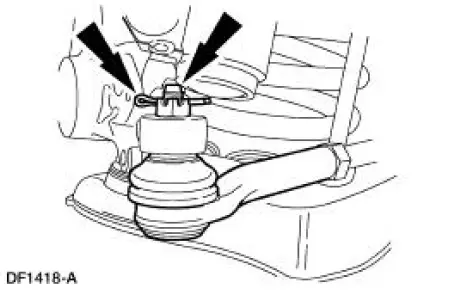
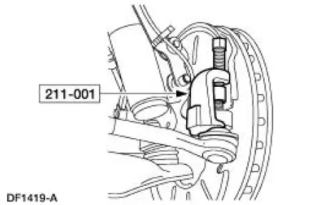
5. CAUTION: Use care not to damage the tie-rod end dust boot.
Using the special tool, disconnect the tie-rod from the spindle.
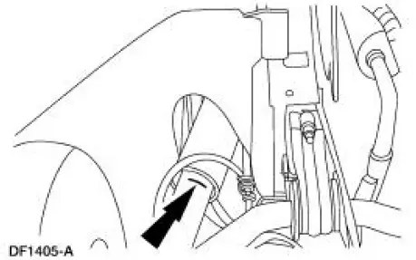
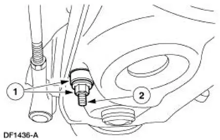
6. Disconnect the front stabilizer bar link (5K483) from the front suspension lower arm (3078).
1. Remove the nut and bushing.
2. Disconnect the link.
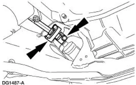
7. CAUTION: Do not allow the intermediate shaft to rotate while it is disconnected from the gear or damage to the clockspring can occur. If there is evidence that the intermediate shaft has rotated, the clockspring must be removed and recentered.
Remove the bolt and disconnect the intermediate shaft from the gear.
- Discard the bolt.
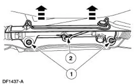
8. CAUTION: Correctly support the power rack and pinion steering gear to avoid damaging the gear and hoses.
Position the power rack and steering gear out of the way.
1. Remove the nuts and bolts.
2. Position the steering gear so the front suspension lower arm front bolt can be removed.
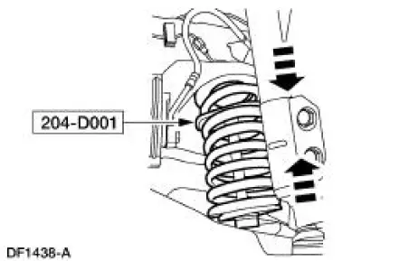
9. Support the front suspension lower arm with a jack stand inboard of the spring seat.
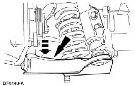
10. NOTE: Note position of the front coil spring (5310) in the lower arm spring seat. It must be installed in the same position.
Using the special tool, compress the spring until it is loose in the spring insulator (5415).
11. Remove the front suspension lower arm pivot nuts and bolts.
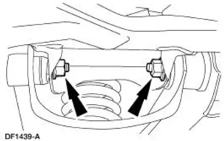
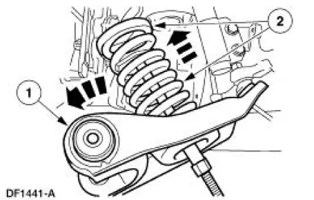
12. Lower the front suspension lower arm and remove the jack stand.
13. Remove the spring.
1. Swing the front suspension lower arm out of the fender well.
2. Remove the spring and the spring insulator.
 Spring
Special Tool(s)
Tie-Rod End Remover
211-001 (TOOL-3290-D) or
Equivalent
Coil Spring Compressor
204-D001 (D78P-5310-A) or
Equivalent
...
 Installation
1. Install the spring.
1. Position the spring and spring insulator in the front suspension lower
control arm.
2. Swing the arm into the fender well.
2. Position a jack stand under the front su ...
Other materials:
Brake Booster - Hydro-Boost (Removal and Installation)
Special Tool(s)
Installer Set, Teflon Seal
211-D027 (D90P-3517-A) or
equivalent
Removal
WARNING: The power brake booster should not be carried by the
accumulator, nor
should it ever be dropped on the accumulator. Check the snap ring on th ...
Transmission fluid check
Checking Automatic Transmission Fluid
Note: Transmission fluid should be checked and, if required, added by
an authorized dealer.
The automatic transmission does not have a transmission fluid dipstick.
See your Scheduled Maintenance Information for scheduled ...
Seats (Description and Operation)
Seats - Front Power
The front power seat features:
a six-way seat regulator control switch (14A701) located on the
front of the seat.
a seat track (61705) mounted under the seat.
a seat regulator motor (14547) and gear housing mounted on ...
