Ford Mustang (1999-2004) Service Manual: Pinpoint Test C: LFC 29/DTC C1414 - Incorrect Vehicle Identification Code
Normal Operation
The restraints control module (RCM) monitors the electrical state of pins 10, 13 and 14 to determine if it is installed on the correct vehicle. If the RCM detects an incorrect condition on any of these pins, it will store a diagnostic trouble code (DTC) C1414 in memory and flash a lamp fault code (LFC) 29 (or higher priority code if one exists) on the air bag indicator.
Possible Causes
An incorrect vehicle identification code can be caused by:
- an RCM installed on the wrong vehicle.
- an incorrectly programmed RCM.
- vehicle ID pins not connected as expected.
PINPOINT TEST C: LFC 29/DTC C1414 - INCORRECT VEHICLE IDENTIFICATION CODE
| Test Step | Result / Action to Take |
| C1 CHECK FOR A HARD OR INTERMITTENT DTC | Yes This is a hard fault. The fault condition is still present. This fault cannot be cleared until it is corrected and the DTC is no longer retrieved during the ondemand self test. GO to C2 . No This is an intermittent fault. The fault condition is not present at this time. GO to C5 . |
|
|
| C2 CHECK THE VEHICLE IDENTIFICATION PINS NO. 1 AND NO. 2 | Yes GO to C3 . No REPAIR any concern found at the RCM C2041 pin 10 and pin 13 connector slots. GO to C6 . |
| WARNING: If the supplemental restraint system
(SRS) is
being serviced, the system must be deactivated and restraint
system diagnostic tools must be installed. Refer to Air Bag
Supplemental Restraint System (SRS) in this section. The air bag restraint system diagnostic tools must be removed and the air bag modules reconnected when the system is reactivated to avoid non-deployment in a collision, resulting in possible personal injury. NOTE: Diagnostics or repairs are not to be performed on a seat equipped with a seat side air bag with the seat in the vehicle. Prior to attempting to diagnose or repair a seat concern when equipped with a seat side air bag, the seat must be removed from the vehicle and the restraint system diagnostic tools must be installed in the seat side air bag electrical connectors. The restraint system diagnostic tools must be removed prior to operating the vehicle over the road. NOTE: After diagnosing or repairing an SRS, the restraint system diagnostic tools must be removed before operating the vehicle over the road. NOTE: After diagnosing or repairing a seat system, the restraint system diagnostic tools must be removed before operating the vehicle over the road. NOTE: The SRS must be fully operational and free of faults before releasing the vehicle to the customer. NOTE: For this vehicle application, RCM C2041 pins 10 and 13 should be open circuited.
|
|
| C3 CHECK THE VEHICLE IDENTIFICATION PIN NO. 3 | Yes GO to C4 . No REPAIR the circuit. GO to C6 |
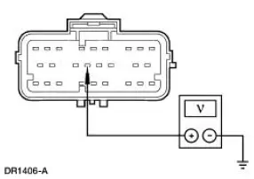
NOTE: For this vehicle application, RCM C2041 pin 14, circuit 611 (WH/OG) should be connected to ignition voltage.
|
|
| C4 CHECK THE RCM PROGRAMMED VEHICLE ID | Yes GO to C5 . No INSTALL a new RCM. GO to C6 |
|
|
| C5 CHECK FOR AN INTERMITTENT FAULT | Yes CHECK for causes of an intermittent open on circuit 611 (WH/OG). Attempt to recreate the hard fault by flexing the wire harness and cycling the ignition key frequently. REPAIR any intermittent concerns found. GO to C6 . No GO to C6 . |
|
|
| C6 CHECK FOR ADDITIONAL DTCs | Yes Do not clear any DTCs until all DTCs have been resolved. GO to the Restraints Control Module (RCM) Diagnostic Trouble Code (DTC) Priority Table in this section for pinpoint test direction. No RECONNECT the system. REACTIVATE the system. PROVE OUT the system. REFER to Air Bag Supplemental Restraint System (SRS) in this section. CLEAR all DTCs. |
|
 Pinpoint Test B: LFC 21/DTC B1921 - RCM Bracket Ground Resistance High
Normal Operation
WARNING: The tightening torque of the restraints control module
(RCM) retaining bolts is
critical for proper air bag supplemental restraint system (SRS)
operation. Refer to ...
 Pinpoint Test D: LFC 15/DTC B 1887- Driver Air Bag Circuit Shorted to
Ground
Pinpoint Test D: LFC 15/DTC B 1887- Driver Air Bag Circuit Shorted to
Ground
Normal Operation
The restraints control module (RCM) checks for driver air bag circuit
shorts to ground by monitoring the
voltage of circuits 614 (GY/OG) and 615 (GY/WH) at pins 3 and 4. If the RC ...
Other materials:
Axle Housing Bushing
Special Tool(s)
Axle Suspension Bushing Set
204-S030 (T78P-5638-A)
Removal
CAUTION: Suspension fasteners are critical parts because they affect
performance of vital
components and systems and their failure can result in major service expense. ...
Starting System (Description and Operation)
Starter Motor
The starter motor is a 12-volt unit that has the starter solenoid mounted on
the drive end housing and
functions as follows:
The current flows through the solenoid energizing coil until the
solenoid plunger is at the end of
its travel.
The ...
Accelerator Cable Bracket - Supercharged Engine
Removal and Installation
1. Disconnect the accelerator cable and speed control cable.
2. Depress the tabs and disconnect the accelerator cable and speed control
cable from the
accelerator cable bracket
3. Remove the bolts and the accelerator cable bracket ...
