Ford Mustang (1999-2004) Service Manual: Pinpoint Test B: LFC 21/DTC B1921 - RCM Bracket Ground Resistance High
Normal Operation
WARNING: The tightening torque of the restraints control module (RCM) retaining bolts is critical for proper air bag supplemental restraint system (SRS) operation. Refer to Restraints Control Module (RCM) in this section for correct torque values.
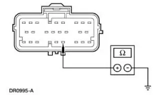
The restraints control module (RCM) monitors the resistance between the ground connections at its housing and the reference ground at pin 21. If the RCM detects a resistance greater than 100 ohms, it will store a diagnostic trouble code (DTC) B1921 in memory and flash a lamp fault code (LFC) 21 (or higher priority code if one exists) on the air bag indicator.
Possible Causes
High resistance between the RCM housing ground and pin ground can be caused by:
- incorrect seating of the RCM retaining bolts.
- incorrect tightening torque of the RCM retaining bolts.
- high resistance on RCM logic ground circuit 397 (BK/WH).
PINPOINT TEST B: LFC 21/DTC B1921 - RCM BRACKET GROUND RESISTANCE HIGH
| Test Step | Result / Action to Take |
| B1 CHECK FOR A HARD OR INTERMITTENT DTC | Yes This is a hard fault. The fault condition is still present. This fault cannot be cleared until it is corrected and the DTC is no longer retrieved during the on-demand self test. GO to B2 . No This is an intermittent fault. The fault condition is not present at this time. GO to B6 . |
|
|
| B2 INSPECT THE RCM MOUNTING, MOUNTING BRACKET AND MOUNTING SURFACE | Yes Make sure the RCM, mounting bracket and mounting surface are free of damage, corrosion or dirt and the three retaining bolts are fully seated and correctly tightened. Reattach the RCM and mounting bracket to the mounting surface. GO to B7 . No GO to B3 . |
|
|
| B3 CHECK THE RCM HARNESS CONNECTION | Yes GO to B4 . No ATTACH the RCM harness connector correctly. GO to B7 . |
|
|
| B4 CHECK THE VEHICLE CHASSIS GROUND | Yes REPAIR the chassis grounding system. GO to B7 . No GO to B5 . |
|
|
| B5 CHECK THE GROUND CIRCUIT 397 (BK/WH) FOR AN OPEN | Yes REPAIR the circuit. GO to B7 . No INSTALL a new RCM. GO to B7 . |
|
|
| B6 CHECK FOR AN INTERMITTENT FAULT | Yes CHECK for causes or intermittent high resistance on circuit 397 (BK/WH). Attempt to recreate the hard fault by flexing the wire harness and cycling the ignition key frequently. REPAIR any intermittent concerns found. GO to B7 . No GO to B7 . |
|
|
| B7 CHECK FOR ADDITIONAL DTCs | Yes Do not clear any DTCs until all DTCs have been resolved. GO to the Restraints Control Module (RCM) Diagnostic Trouble Code (DTC) Priority Table in this section for pinpoint test direction. No RECONNECT the system. REACTIVATE the system. PROVE OUT the system. REFER to Air Bag Supplemental Restraint System (SRS) in this section. CLEAR all DTCs. |
|
 Pinpoint Test A: The Air Bag Warning Indicator Is Illuminated Continuously
- RCM
Disconnected, Inoperative or Lost/Low Ignition Feed
Pinpoint Test A: The Air Bag Warning Indicator Is Illuminated Continuously
- RCM
Disconnected, Inoperative or Lost/Low Ignition Feed
Normal Operation
NOTE: During normal operation the air bag indicator will be lit continuously
for 6 seconds after the
ignition switch is placed in the RUN position and after five cycles of a lamp
fa ...
 Pinpoint Test C: LFC 29/DTC C1414 - Incorrect Vehicle Identification Code
Normal Operation
The restraints control module (RCM) monitors the electrical state of pins
10, 13 and 14 to determine if
it is installed on the correct vehicle. If the RCM detects an incorrect
c ...
Other materials:
Universal Garage Door Opener (If Equipped)
UNIVERSAL GARAGE DOOR OPENER
The appearance of your vehicle’s universal garage door opener will
vary according to your option package. Before programing, make sure
you identify which transmitter you have by comparing it to the graphics
below.
HomeLink®
Ca ...
Torque Converter Cleaning And Inspection
Material
Item
Specification
MERCON V Automatic
Transmission Fluid
XT-5-QM, XT-5-DM
MERCON V
1. If a new torque converter is being installed, continue with Substep 2 of
Step 2.
2. If a new torque converter is not being installed, the fol ...
Instrument Cluster (Description and Operation)
The instrument cluster (10849) consists of the following components:
Instrument Cluster-Base 3.8L Engine
Instrument Cluster-Base 4.6L Engine
Instrument Cluster-Cobra
...
