Ford Mustang (1999-2004) Service Manual: Pinpoint Test H: LFC 32/DTC B1932 - Driver Air Bag Circuit Resistance High
Normal Operation
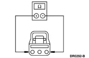
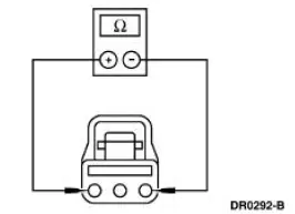
The restraints control module (RCM) monitors the resistance for the driver air bag ignitor by measuring the resistance between pins 3 and 4. If the RCM detects high resistance between these pins, it will store a diagnostic trouble code (DTC) B1932 in memory and flash a lamp fault code (LFC) 32 (or higher priority code if one exists) on the air bag indicator.
Possible Causes
Driver air bag high resistance can be caused by:
- a poor connection or corrosion in the driver air bag module circuits or the clockspring.
- an open circuit or high resistance in the clockspring windings.
- an open circuit or high resistance in the wiring harness.
- an open circuit or high resistance in the driver air bag module.
- an RCM internal concern.
PINPOINT TEST H: LFC 32/DTC B1932 - DRIVER AIR BAG CIRCUIT RESISTANCE HIGH
| Test Step | Result / Action to Take |
| H1 CHECK FOR A HARD OR INTERMITTENT DTC | Yes This is a hard fault. The fault condition is still present. This fault cannot be cleared until it is corrected and the DTC is no longer retrieved during the on-demand self test. GO to H2 . No This is an intermittent fault. The fault condition is not present at this time. GO to H5 . |
|
|
| H2 CHECK THE DRIVER AIR BAG MODULE | Yes GO to H3 . No INSTALL a new driver air bag module. GO to H6 . |
| WARNING: If the supplemental restraint system
(SRS) is
being serviced, the system must be deactivated and restraint
system diagnostic tools must be installed. Refer to Air Bag
Supplemental Restraint System (SRS) in this section.
The air bag restraint system diagnostic tools must be removed and the air bag modules reconnected when the system is reactivated to avoid non-deployment in a collision, resulting in possible personal injury. NOTE: Diagnostics or repairs are not to be performed on a seat equipped with a seat side air bag with the seat in the vehicle. Prior to attempting to diagnose or repair a seat concern when equipped with a seat side air bag, the seat must be removed from the vehicle and the restraint system diagnostic tools must be installed in the seat side air bag electrical connectors. The restraint system diagnostic tools must be removed prior to operating the vehicle over the road. NOTE: After diagnosing or repairing an SRS, the restraint system diagnostic tools must be removed before operating the vehicle over the road. NOTE: After diagnosing or repairing a seat system, the restraint system diagnostic tools must be removed before operating the vehicle over the road. NOTE: The SRS must be fully operational and free of faults before releasing the vehicle to the customer.
|
|
| H3 CHECK THE DRIVER AIR BAG MODULE CIRCUIT | Yes GO to H4 . No INSTALL a new RCM. GO to H6 . |
|
|
| H4 CHECK THE CLOCKSPRING | Yes INSTALL a new clockspring. GO to H6 . No REPAIR the circuit (s) as necessary. GO to H6 . |
|
|
| H5 CHECK FOR AN INTERMITTENT FAULT | Yes CHECK for causes of intermittent high resistance on circuit 614 (GY/OG), circuit 615 (GY/WH), and the clockspring assembly. Attempt to recreate the hard fault by flexing the wire harness and cycling the ignition key frequently. REPAIR any intermittent concerns found. GO to H6 . No GO to H6 . |
|
|
| H6 CHECK FOR ADDITIONAL DTCs | Yes Do not clear any DTCs until all DTCs have been resolved. GO to the Restraints Control Module (RCM) Diagnostic Trouble Code (DTC) Priority Table in this section for pinpoint test direction. No RECONNECT the system. REACTIVATE the system. PROVE OUT the system. REFER to Air Bag Supplemental Restraint System (SRS) in this section. CLEAR all DTCs. |
|
 Pinpoint Test G: LFC 16/DTC B1925 - Passenger Air Bag Circuit Shorted to
Battery or Ignition
Pinpoint Test G: LFC 16/DTC B1925 - Passenger Air Bag Circuit Shorted to
Battery or Ignition
Normal Operation
The restraints control module (RCM) checks for passenger air bag circuit
shorts to battery or ignition
by monitoring the voltage of circuits 607 (LB/OG) and 616 (PK/BK) at pins 6 ...
 Pinpoint Test I: LFC 33/DTC B1933 - Passenger Air Bag Circuit Resistance
High
Pinpoint Test I: LFC 33/DTC B1933 - Passenger Air Bag Circuit Resistance
High
Normal Operation
The restraints control module (RCM) monitors the resistance of the
passenger air bag ignitor by
measuring the resistance between pins 6 and 7. If the RCM detects high
resistance ...
Other materials:
Heated windows and mirrors (if equipped)
Heated Rear Window
Note: The vehicle must be running to use this feature.
Press the control to clear the rear window of thin ice and fog. Press the
control again within 15 minutes to switch it off. It turns off automatically
after approximately 15 minutes, or ...
Accelerator Cable Bracket - 3.8L
Removal and Installation
1. Disconnect the speed control cable from the throttle body and the bracket.
For additional
information, refer to Section.
2. Disconnect the accelerator cable from the throttle body by rotating the
throttle body full open
and align ...
Disassembly
1. WARNING: To avoid risk of serious personal injury, follow all
warnings, cautions,
notes and instructions in the driver air bag removal and installation procedure.
Remove the steering column (3C529). For additional information, refer to Column
in this
s ...
