Ford Mustang (1999-2004) Service Manual: Pinpoint Test I: LFC 33/DTC B1933 - Passenger Air Bag Circuit Resistance High
Normal Operation
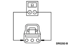
The restraints control module (RCM) monitors the resistance of the passenger air bag ignitor by measuring the resistance between pins 6 and 7. If the RCM detects high resistance between these pins, it will store a diagnostic trouble code (DTC) B1933 in memory and flash a lamp fault code (LFC) 33 (or higher priority code if one exists) on the air bag indicator.
Possible Causes
A passenger air bag high resistance can be caused by:
- a poor connection or corrosion in the passenger air bag module circuits.
- an open circuit or high resistance in the wiring harness.
- an open circuit or high resistance in the passenger air bag module.
- an RCM internal concern.
PINPOINT TEST I: LFC 33/DTC B1933 - PASSENGER AIR BAG CIRCUIT RESISTANCE HIGH
| Test Step | Result / Action to Take |
| I1 CHECK FOR A HARD OR INTERMITTENT DTC | Yes This is a hard fault. The fault condition is still present. This fault cannot be cleared until it is corrected and the DTC is no longer retrieved during the on-demand self test. GO to I2 . No This is an intermittent fault. The fault condition is not present at this time. GO to I4 |
|
|
| I2 CHECK THE PASSENGER AIR BAG MODULE | Yes GO to I3 . No INSTALL a new passenger air bag module. GO to I5 . |
| WARNING: If the supplemental restraint system
(SRS) is
being serviced, the system must be deactivated and restraint
system diagnostic tools must be installed. Refer to Air Bag
Supplemental Restraint System (SRS) in this section.
The air bag restraint system diagnostic tools must be removed and the air bag modules reconnected when the system is reactivated to avoid non-deployment in a collision, resulting in possible personal injury. NOTE: Diagnostics or repairs are not to be performed on a seat equipped with a seat side air bag with the seat in the vehicle. Prior to attempting to diagnose or repair a seat concern when equipped with a seat side air bag, the seat must be removed from the vehicle and the restraint system diagnostic tools must be installed in the seat side air bag electrical connectors. The restraint system diagnostic tools must be removed prior to operating the vehicle over the road. NOTE: After diagnosing or repairing an SRS, the restraint system diagnostic tools must be removed before operating the vehicle over the road. NOTE: After diagnosing or repairing a seat system, the restraint system diagnostic tools must be removed before operating the vehicle over the road. NOTE: The SRS must be fully operational and free of faults before releasing the vehicle to the customer.
|
|
| I3 CHECK THE PASSENGER AIR BAG MODULE CIRCUIT | Yes REPAIR the circuit (s) as necessary. GO to I5 . No INSTALL a new RCM. GO to I5 . |
|
|
| I4 CHECK FOR AN INTERMITTENT FAULT | Yes CHECK for causes of intermittent high resistance on circuit 607 (LB/OG) and circuit 616 (PK/BK). Attempt to recreate the hard fault by flexing the wire harness and cycling the ignition key frequently. REPAIR any intermittent concerns found. GO to I5 . No GO to I5 . |
|
|
| I5 CHECK FOR ADDITIONAL DTCs | Yes Do not clear any DTCs until all DTCs have been resolved. GO to the Restraints Control Module (RCM) Diagnostic Trouble Code (DTC) Priority Table in this section for pinpoint test direction. No RECONNECT the system. REACTIVATE the system. PROVE OUT the system. REFER to Air Bag Supplemental Restraint System (SRS) in this section. CLEAR all DTCs. |
|
 Pinpoint Test H: LFC 32/DTC B1932 - Driver Air Bag Circuit Resistance High
Normal Operation
The restraints control module (RCM) monitors the resistance for the
driver air bag ignitor by measuring
the resistance between pins 3 and 4. If the RCM detects high resistance
b ...
 Pinpoint Test J: LFC 34/DTC B1934 - Driver Air Bag Circuit Resistance Low
Normal Operation
The restraints control module (RCM) monitors the resistance of the driver
air bag ignitor by measuring
the resistance between pins 3 and 4. If the RCM detects low resistance
bet ...
Other materials:
Removal
WARNING: Do not smoke or carry lighted tobacco or open flame of any
type when
working on or near any fuel related components. Highly flammable mixtures are
always present
and can ignite. Failure to follow these instructions can result in personal
injury.
1. ...
Supercharger Cooling
General Specifications
a - Use the same type coolant that was drained from the cooling system.
Do not mix coolant types.
b - The addition of Motorcraft Cooling System Stop Leak Pellets, VC-6,
darkens Motorcraft Premium
Gold Engine Coolant from yell ...
Engine (Removal)
Special Tool(s)
Special Tool(s)
Support Bracket, Engine
303-639
Spreader Bar
303-D089 (D93P-6001-A3)
Lifting Bracket Set, Engine
303-D074 (D91P-6001-A)
Removal
1. Remove the hood.
2. Remove the battery. For additi ...
