Ford Mustang (1999-2004) Service Manual: Pinpoint Test J: LFC 34/DTC B1934 - Driver Air Bag Circuit Resistance Low
Normal Operation
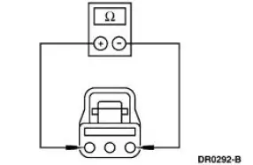
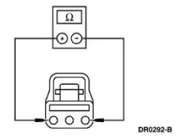
The restraints control module (RCM) monitors the resistance of the driver air bag ignitor by measuring the resistance between pins 3 and 4. If the RCM detects low resistance between these pins, it will store a diagnostic trouble code (DTC) B1934 in memory and flash a lamp fault code (LFC) 34 (or higher priority code if one exists) on the air bag indicator.
Possible Causes
Driver air bag low resistance can be caused by:
- a short in the clockspring windings.
- a short in the wiring harness.
- a low resistance in the driver air bag module.
- an RCM internal concern.
- worn or damaged short bar or camming beam.
PINPOINT TEST J: LFC 34/DTC B1934 - DRIVER AIR BAG CIRCUIT RESISTANCE LOW
| Test Step | Result / Action to Take |
| J1 CHECK FOR A HARD OR INTERMITTENT DTC | Yes This is a hard fault. The fault condition is still present. This fault cannot be cleared until it is corrected and the DTC is no longer retrieved during the on-demand self test. GO to J2 . No This is an intermittent fault. The fault condition is not present at this time. GO to J5 . |
|
|
| J2 CHECK THE DRIVER AIR BAG MODULE | Yes GO to J3 . No INSTALL a new driver air bag module. GO to J6 . |
| WARNING: If the supplemental restraint system
(SRS) is
being serviced, the system must be deactivated and restraint
system diagnostic tools must be installed. Refer to Air Bag
Supplemental Restraint System (SRS) in this section.
The air bag restraint system diagnostic tools must be removed and the air bag modules reconnected when the system is reactivated to avoid non-deployment in a collision, resulting in possible personal injury. NOTE: Diagnostics or repairs are not to be performed on a seat equipped with a seat side air bag with the seat in the vehicle. Prior to attempting to diagnose or repair a seat concern when equipped with a seat side air bag, the seat must be removed from the vehicle and the restraint system diagnostic tools must be installed in the seat side air bag electrical connectors. The restraint system diagnostic tools must be removed prior to operating the vehicle over the road. NOTE: After diagnosing or repairing an SRS, the restraint system diagnostic tools must be removed before operating the vehicle over the road. NOTE: After diagnosing or repairing a seat system, the restraint system diagnostic tools must be removed before operating the vehicle over the road. NOTE: The SRS must be fully operational and free of faults before releasing the vehicle to the customer.
|
|
| J3 CHECK THE DRIVER AIR BAG MODULE CIRCUIT | Yes INSTALL a new RCM. GO to J6 . No GO to J4 . |
|
|
| J4 CHECK THE CLOCKSPRING | Yes INSTALL a new clockspring. GO to J6 . No REPAIR the circuit (s) as necessary. GO to J6 . |
|
|
| J5 CHECK FOR AN INTERMITTENT FAULT | Yes CHECK for causes of intermittent low resistance on circuit 614 (GY/OG), circuit 615 (GY/WH), and the clockspring assembly. Attempt to recreate the hard fault by flexing the wire harness and cycling the ignition key frequently. REPAIR any intermittent concerns found. GO to J6 . No GO to J6 . |
|
|
| J6 CHECK FOR ADDITIONAL DTCs | Yes Do not clear any DTCs until all DTCs have been resolved. GO to the Restraints Control Module (RCM) Diagnostic Trouble Code (DTC) Priority Table in this section for pinpoint test direction. No RECONNECT the system. REACTIVATE the system. PROVE OUT the system. REFER to Air Bag Supplemental Restraint System (SRS) in this section. CLEAR all DTCs. |
|
 Pinpoint Test I: LFC 33/DTC B1933 - Passenger Air Bag Circuit Resistance
High
Pinpoint Test I: LFC 33/DTC B1933 - Passenger Air Bag Circuit Resistance
High
Normal Operation
The restraints control module (RCM) monitors the resistance of the
passenger air bag ignitor by
measuring the resistance between pins 6 and 7. If the RCM detects high
resistance ...
 Pinpoint Test K: LFC 35/DTC B1935 - Passenger Air Bag Circuit Resistance
Low
Pinpoint Test K: LFC 35/DTC B1935 - Passenger Air Bag Circuit Resistance
Low
Normal Operation
The restraints control module (RCM) monitors the resistance of the
passenger air bag ignitor by
measuring the resistance between pins 6 and 7. If the RCM detects low
resistance ...
Other materials:
Fuel Tank Filler Pipe
Removal
1. Remove the fuel tank. For additional information, refer to Fuel Tank in
this section.
2. Remove the bolts from the filler pipe housing.
3. Remove the bolts from the filler pipe rubber boot-to-floor pan.
4. Remove the hose attached to the upper p ...
Windshield Glass
Special Tool(s)
Rotunda Pneumatic Knife with
Offset Blade
107-R1511 or equivalent
The Pumper
164-R2459 or equivalent
Rotunda Interior Auto Glass
Cut-Out Knife Kit
164-R2450 or equivalent
...
Transmission (Removal)
1. Disconnect the battery ground cable. For additional information, refer
to Section.
2. Lift up on the clutch pedal and secure it in place.
3. Remove the gearshift lever knob (7213).
4. Remove the console panel gearshift plate. Lift the gearshift leve ...
