Ford Mustang (1999-2004) Service Manual: Transmission (Removal)
1. Disconnect the battery ground cable. For additional information, refer to Section.
2. Lift up on the clutch pedal and secure it in place.
3. Remove the gearshift lever knob (7213).
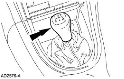
4. Remove the console panel gearshift plate. Lift the gearshift lever boot over the gearshift lever (7210).
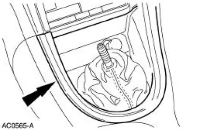
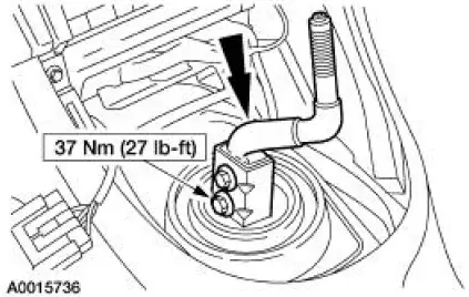
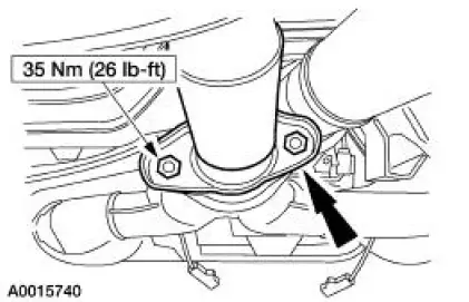
5. Remove the bolts and the shift lever.
6. Raise and support the vehicle.
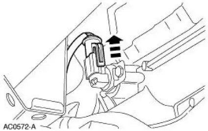
7. Disconnect the heated oxygen sensor electrical connectors.
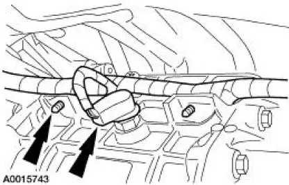
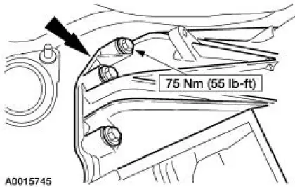
8. Remove the nuts. Position and secure the muffler and tailpipe out of the way.
9. Remove the LH nuts.
10. Remove the RH nuts.
11. Remove the dual converter Y-pipe.
12. CAUTION: Index-mark the driveshaft flange and pinion flange, and the driveshaft slip yoke and transmission output shaft.
13. Disconnect the reversing lamp switch electrical connector. Disconnect the wiring harness from the transmission.
14. Remove the starter motor (11001). For additional information, refer to Section.
15. Disconnect the output shaft speed sensor (OSS) electrical connector. Disconnect the wiring harness from the transmission.
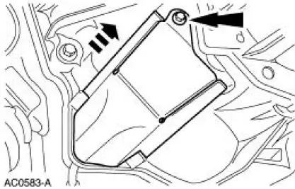
16. Remove the bolt and the clutch release lever cover.
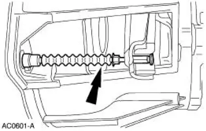
17. CAUTION: To prevent damage, do not depress the clutch pedal with the transmission removed.
Disengage the clutch release cable from the clutch release fork.
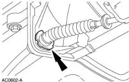
18. Remove the clutch cable retainer and remove the clutch cable from the transmission.
19. If transmission disassembly is necessary, drain the transmission fluid.
20. Position a transmission jack and support the transmission.
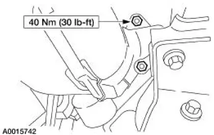
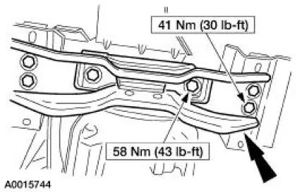
21. Remove the bolts and the transmission crossmember.
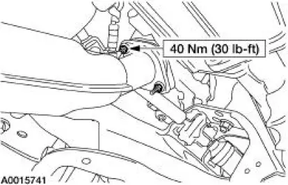
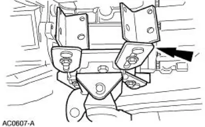
22. Remove the bolts.
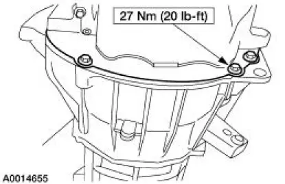
23. Lower the transmission and remove the five bolts.
 Transmission (Disassembly)
Special Tool(s)
Bearing Puller
205-D064 (D84L-1123-A) or
Equivalent
Front Hub Tool
204-069 (T81P-1104-C)
Holding Fixture
307-003 (T57L-500-B)
Imp ...
Other materials:
Refueling
WARNING: Fuel vapor burns violently and a fuel fire can cause
severe injuries. To help avoid injuries to you and others:
• Read and follow all the instructions on the pump island.
• Turn off your engine when you are refueling.
• Do not smoke if you are n ...
Satellite radio information
Satellite Radio Channels
Sirius broadcasts a variety of music, news, sports, weather, traffic and
entertainment satellite radio channels. For more information and a
complete list of Sirius satellite radio channels, visit www.siriusxm.com in the
United States, ...
Final assembly
23. Install the differential assembly in the differential housing. For
additional information, refer to
Differential Case in this section.
24. CAUTION: Align the index marks.
CAUTION: Install the driveshaft with new bolts. If new bolts are not available,
a ...
