Ford Mustang (1999-2004) Service Manual: Pinpoint Test K: LFC 35/DTC B1935 - Passenger Air Bag Circuit Resistance Low
Normal Operation
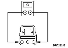
The restraints control module (RCM) monitors the resistance of the passenger air bag ignitor by measuring the resistance between pins 6 and 7. If the RCM detects low resistance between these pins, it will store a diagnostic trouble code (DTC) B1935 in memory and flash a lamp fault code (LFC) 35 (or higher priority code if one exists) on the air bag indicator.
Possible Causes
Passenger air bag low resistance can be caused by:
- a short in the wiring harness.
- a low resistance in the passenger air bag module.
- an RCM internal concern.
- a worn or damaged connector shorting bar or camming beam.
PINPOINT TEST K: LFC 35/DTC B1935 - PASSENGER AIR BAG CIRCUIT RESISTANCE LOW
| Test Step | Result / Action to Take |
| K1 CHECK FOR A HARD OR INTERMITTENT DTC | Yes This is a hard fault. The fault condition is still present. This fault cannot be cleared until it is corrected and the DTC is no longer retrieved during the on-demand self test. GO to K2 . No This is an intermittent fault. The fault condition is not present at this time. GO to K4 . |
|
|
| K2 CHECK THE PASSENGER AIR BAG MODULE | Yes GO to K3 . No INSTALL a new passenger air bag module. GO to K5 . |
| WARNING: If the supplemental restraint system
(SRS) is
being serviced, the system must be deactivated and restraint
system diagnostic tools must be installed. Refer to Air Bag
Supplemental Restraint System (SRS) in this section.
The air bag restraint system diagnostic tools must be removed and the air bag modules reconnected when the system is reactivated to avoid non-deployment in a collision, resulting in possible personal injury. NOTE: Diagnostics or repairs are not to be performed on a seat equipped with a seat side air bag with the seat in the vehicle. Prior to attempting to diagnose or repair a seat concern when equipped with a seat side air bag, the seat must be removed from the vehicle and the restraint system diagnostic tools must be installed in the seat side air bag electrical connectors. The restraint system diagnostic tools must be removed prior to operating the vehicle over the road. NOTE: After diagnosing or repairing an SRS, the restraint system diagnostic tools must be removed before operating the vehicle over the road. NOTE: After diagnosing or repairing a seat system, the restraint system diagnostic tools must be removed before operating the vehicle over the road. NOTE: The SRS must be fully operational and free of faults before releasing the vehicle to the customer.
|
|
| K3 CHECK THE PASSENGER AIR BAG MODULE CIRCUIT | Yes INSTALL a new RCM. GO to K5 . No REPAIR the circuit (s) as necessary. GO to K5 . |
|
|
| K4 CHECK FOR AN INTERMITTENT FAULT | Yes CHECK for causes of intermittent low resistance on circuit 607 (LB/OG) and circuit 616 (PK/BK). Attempt to recreate the hard fault by flexing the wire harness and cycling the ignition key frequently. REPAIR any intermittent concerns found. GO to K5 . No GO to K5 . |
|
|
| K5 CHECK FOR ADDITIONAL DTCs | Yes Do not clear any DTCs until all DTCs have been resolved. GO to the Restraints Control Module (RCM) Diagnostic Trouble Code (DTC) Priority Table in this section for pinpoint test direction. No RECONNECT the system. REACTIVATE the system. PROVE OUT the system. REFER to Air Bag Supplemental Restraint System (SRS) in this section. CLEAR all DTCs. |
|
 Pinpoint Test J: LFC 34/DTC B1934 - Driver Air Bag Circuit Resistance Low
Normal Operation
The restraints control module (RCM) monitors the resistance of the driver
air bag ignitor by measuring
the resistance between pins 3 and 4. If the RCM detects low resistance
bet ...
 Pinpoint Test L: B1892 - Air Bag Tone Warning Indicator Circuit Shorted to
Ground or Open
Pinpoint Test L: B1892 - Air Bag Tone Warning Indicator Circuit Shorted to
Ground or Open
Normal Operation
The restraints control module (RCM) monitors its connection to the
generic electronic module (GEM) at
C201e pin 10. This connection is used to signal a chime if the air bag
indi ...
Other materials:
Driveline Angle Inspection
Special Tool(s)
Anglemaster II Driveline
Inclinometer
164-R2402 or equivalent
NOTE: An incorrect driveline angle can cause a vibration or shudder.
1. Check the vehicle for evidence or overload or sagging. Check for specified
air pressures
in ...
Intake Air Distribution and Filtering
Torque Specifications
a - Refer to the procedure
Intake Air Distribution and Filtering (DESCRIPTION AND OPERATION)
The air intake system consists of the:
air intake scoop (Mach I)
air cleaner (ACL).
air cleaner (ACL) element.
mass air flow (MAF) s ...
Anti-Theft - Passive Anti-Theft System (PATS) (Diagnosis and Testing)
Refer to Wiring Diagrams Cell 112 , Anti-Theft for schematic and connector
information.
Refer to Wiring Diagrams Cell 60 , Instrument Cluster for schematic and
connector information.
Special Tool(s)
73III Automotive Meter
105-R0057 or equivalen ...
