Ford Mustang (1999-2004) Service Manual: Pressure
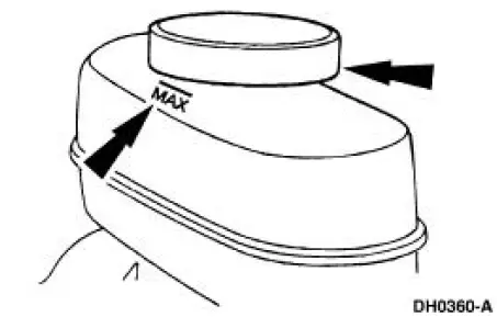
1. Clean all dirt from and remove the brake master cylinder filler cap and fill the brake master cylinder reservoir with the specified brake fluid.
2. NOTE: Master cylinder pressure bleeder adapter tools are available from various manufacturers of pressure bleeding equipment. Follow the instructions of the manufacturer when installing the adapter.
Install the bleeder adapter to the brake master cylinder reservoir, and attach the bleeder tank hose to the fitting on the adapter.
3. NOTE: Bleed the longest line first. Make sure the bleeder tank contains enough specified brake fluid to complete the bleeding operation.
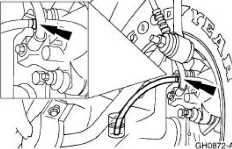
Place a box end wrench on the RH rear bleeder screw. Attach a rubber drain tube to the RH rear bleeder screw, and submerge the free end of the tube in a container partially filled with clean brake fluid.
4. Open the valve on the bleeder tank.
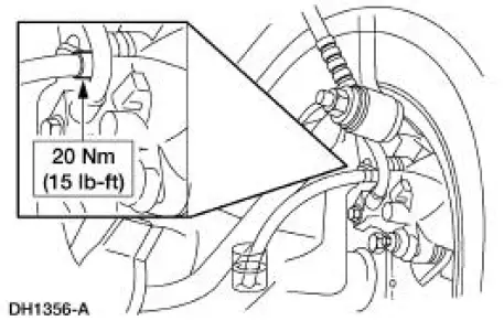
5. Loosen the RH rear bleeder screw. Leave open until clear, bubble-free brake fluid flows, then tighten the RH rear bleeder screw and remove the rubber hose.
6. Continue bleeding the rear of the system, going in order from the LH rear bleeder screw to the RH front disc brake caliper bleeder screw ending with the LH front disc brake caliper bleeder screw.
7. Close the bleeder tank valve. Remove the tank hose from the adapter, and remove the adapter.
Hydraulic Leak Check
1. NOTE: Brake fluid is water soluble and it is possible that all evidence of fluid leakage has been washed off if the vehicle has been operated in the rain or snow.
Make sure the brake master cylinder reservoir (2K478) is full.
2. Apply the brakes several times and make sure the brake pedal (2455) feel is not spongy. If necessary, bleed the system. For additional information, refer to Bleeding-System in this section.
3. If the reservoir level is dropping, inspect the brake components, fittings and lines to locate the source of the leak.
 Manual
WARNING: Brake fluid contains polyglycol ethers and polyglycols.
Avoid contact with
eyes. Wash hands thoroughly after handling. If brake fluid contacts
eyes, flush eyes with
running water fo ...
 Runout Check - Brake Disc and Hub
Special Tool(s)
Brake Measurement Kit
134-R0199 or equivalent
Material
Item
Specification
High Temperature Nickel Anti-
Seize Lubricant
F6AZ-9L494-AA
ESE-M12A4-
A
...
Other materials:
Engine and Radiator Flushing
Special Tool(s)
Coolant System
Drain/Flush/Fill
164-R3673 or equivalent
Flush Kit
164-R3658 or equivalent
Drain Kit
164-R3662 or equivalent
Material
Item
Specification
Motorcraft Premium Cooling
...
Pinpoint Tests
CAUTION: Be careful when probing the CJB, battery junction box (BJB)
or any
connectors. Damage will result to the connector receptacle if the probe or
terminal being used
is too large.
CAUTION: Electronic modules are sensitive to static electrical char ...
Headlamp Adjustment
Headlamp Aiming
1. The headlamp aiming procedure depends on the type of beam pattern the
headlamp is
equipped with. Vehicles may come equipped with visual optical right (VOR),
visual optical left
(VOL), or SAE only (includes sealed beam type) headlamps. ...
