Ford Mustang (1999-2004) Service Manual: Removal
WARNING: Do not smoke or carry lighted tobacco or open flame of any type when working on or near any fuel related components. Highly flammable mixtures are always present and may be ignited. Failure to follow these instructions may result in personal injury.
1. Disconnect the battery ground cable (14301). For additional information, refer to Section.
2. Disconnect the air cleaner outlet tube. For additional information, refer to Section.
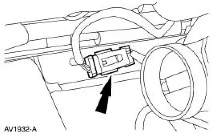
3. Disconnect the 42 pin connector.
4. Separate the wiring harness retainers from the dash panel.
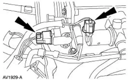
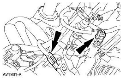
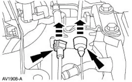
5. Disconnect the following connectors:
- Throttle position (TP) sensor
- Idle air control (IAC) valve
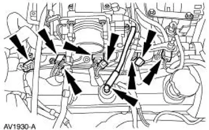
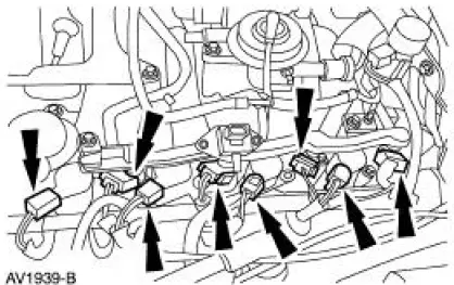
6. Disconnect the following connections:
- Four ignition coils
- Four fuel injectors
- Positive crankcase ventilation (PCV) hose from valve cover.
7. Disconnect the following connectors:
- RH radio ignition interference capacitor
- Engine coolant temperature (ECT) sensor
8. Disconnect the 16 pin connector
9. Raise the vehicle. For additional information, refer to Section.
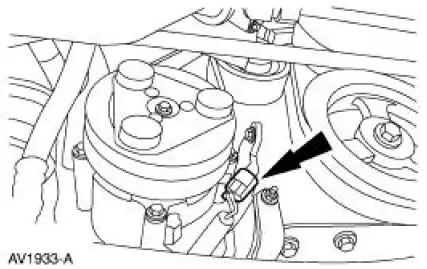
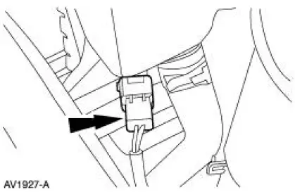
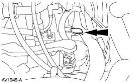
10. Disconnect the crankshaft position (CKP) sensor electrical connector.
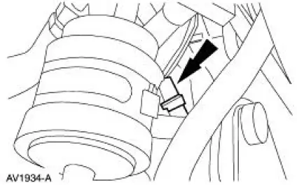
11. Disconnect the A/C compressor clutch electrical connector.
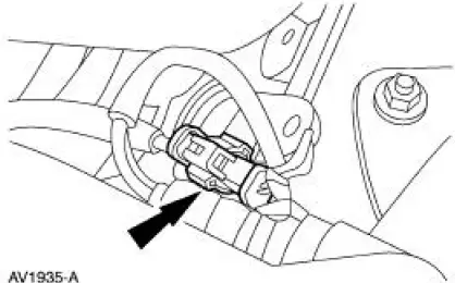
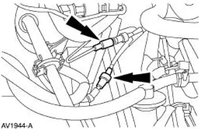
12. Disconnect the RH heated oxygen sensor (HO2S) electrical connector.
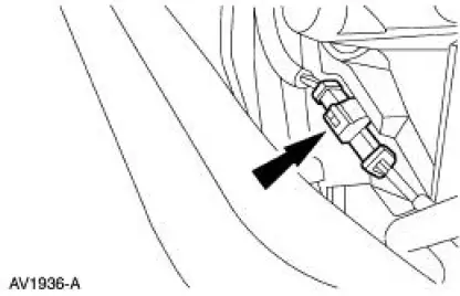
13. Disconnect the LH heated oxygen sensor (HO2S) electrical connector.
14. Lower the vehicle.
15. Disconnect the coolant reservoir electrical connector.
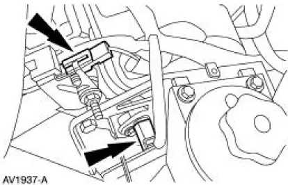
16. Disconnect the following connectors:
- Camshaft position (CMP) sensor
- LH radio ignition interference capacitor
17. Separate the wiring harness from the power steering reservoir bracket.

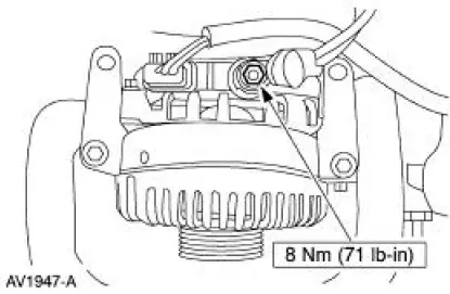
18. Disconnect the generator connectors:
- Battery power supply wire
- Voltage regulator
19. Disconnect the following connectors:
- LH fuel injectors
- LH ignition coils
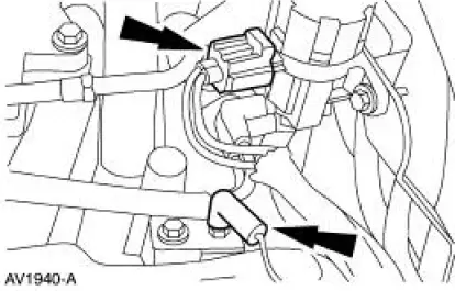
20. Disconnect the following connectors:
- Exhaust vacuum regulator (EVR)
- Ground wire
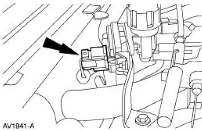
21. Disconnect the EGR pressure transducer electrical connector.
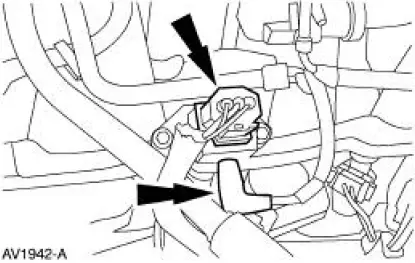
22. Disconnect the fuel pressure sensor electrical connector and the vacuum hose.
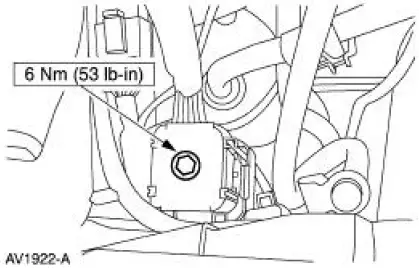
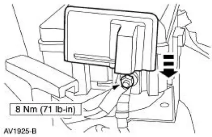
23. Slide cover up and remove the nut and the power distribution box battery supply wire.
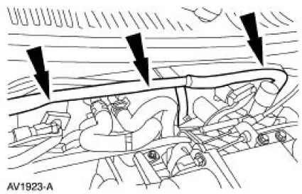
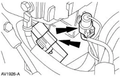
24. NOTE: These two connectors are located under the power distribution box.
Disconnect the two connectors.
25. Disconnect the main vacuum hose.
26. Disconnect the vacuum lines
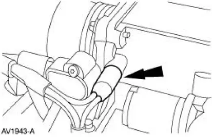
27. Squeeze the two locking tabs, and remove the accelerator cable and the speed control cable (if equipped) from the bracket and position aside.
28. Separate the fuel charging wiring (9D930) from the rear of the intake manifold (9424) and remove from the vehicle.

 Installation
1. Position the fuel charging wiring in the vehicle and attach to the rear of
the intake manifold.
2. NOTE: Make sure the locking clips are fully engaged into the bracket.
Reposition the accel ...
Other materials:
Air Bag Supplemental Restraint System (SRS) (Description and Operation)
The air bag supplemental restraint system (SRS) is designed to provide
increased collision protection
for front seat occupants in addition to that provided by the three-point safety
belt system. Safety belt
use is necessary to obtain the best occupant protec ...
Inspection and Verification
1. Verify the customer's concern by operating the active restraint system to
duplicate the condition.
2. Inspect to determine if any of the following mechanical or electrical
concerns apply:
Visual Inspection Chart
Mechanical
Electrical
...
Wheel
Removal and Installation
1. Disconnect the battery ground cable (14301) and wait at least one minute
to allow the depletion
of the restraint system backup power supply.
2. Turn the steering wheel to the straight-ahead position and the ignition
switch to ...
