Ford Mustang (1999-2004) Service Manual: Assembly
1. NOTE: Lubricate direct clutch piston inner seal and seal protector with petroleum jelly.
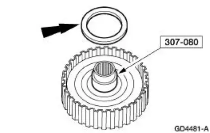
Using the special tool, install the inner piston seal.
- Install the seal with sealing lip facing down.
2. Install the clutch piston outer seal so that when the piston is installed the sealing lip points toward the bottom of the cylinder.
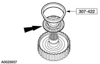
3. NOTE: Coat the inner and outer direct clutch piston seals, clutch cylinder sealing area and piston inner sealing area with petroleum jelly.
Using the special tool, install the direct clutch piston.
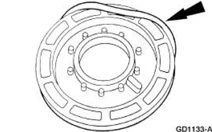
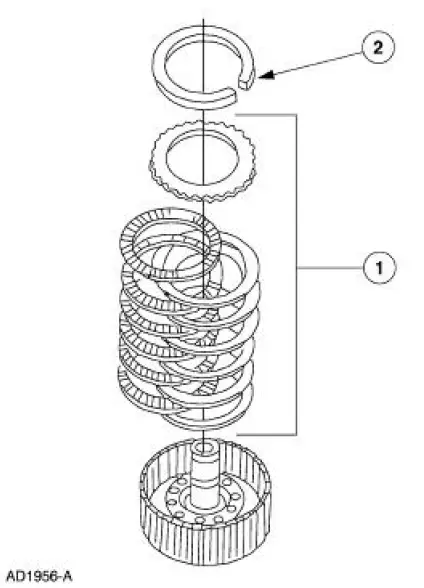
4. Install the piston return spring and retainer assembly.
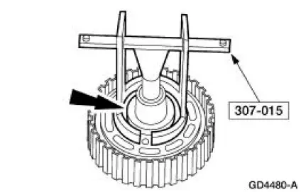
5. Using the special tool, compress the piston return spring and install the retaining ring.
6. NOTE: Before assembly, soak new clutch discs in clean automatic transmission fluid for 15 minutes.
Install the clutch pack retaining ring.
1. Alternate external spline (steel) plates and internal spline (friction) plates, starting with a steel plate and ending with the friction plate.
2. Install the clutch pack retaining ring.
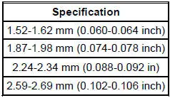
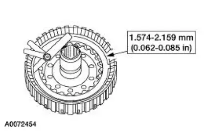
7. Use a feeler gauge to check the clearance between the clutch pack selective retaining ring and the pressure plate.
- If the clearance is not within specifications, install the correct size retaining ring and recheck the clearance.
Selective Retaining Ring
8. Install the direct clutch hub.
1. Install the No.7 direct clutch inner bearing support.
2. Install the direct clutch hub.
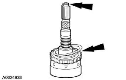
NOTE: Inspect the output shaft bearing surfaces for scores. Inspect the output shaft splines for wear.
Inspect all bushings.
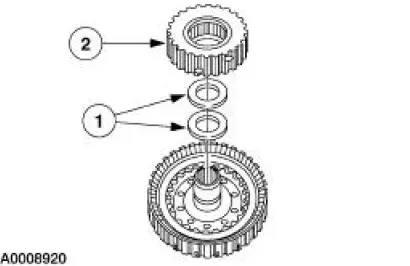
9. CAUTION: Make sure the seals are lapped correctly. Internal damage may occur.
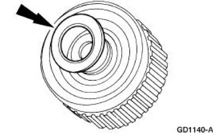
Install the two direct clutch seal rings.

10. Install the output shaft hub.
- Position the output shaft hub.
- Install the retaining ring.
11. Install the three output shaft seal rings.
12. Install the No. 8 needle bearing on the direct clutch cylinder.
13. NOTE: Direct clutch cylinder may be installed after the output shaft ring gear is installed to the output shaft hub.
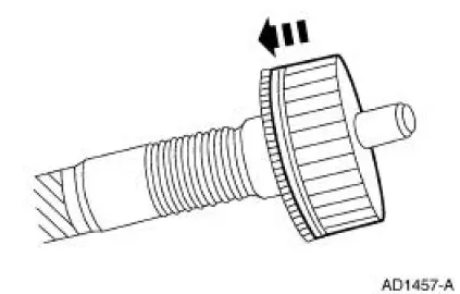
Assemble the direct clutch on the output shaft.
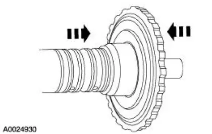
14. CAUTION: The index mark on the output shaft must be aligned with the index mark on the output shaft ring gear.
Align the index marks on output shaft and the output shaft ring gear and install the ring gear on the output shaft.
 Disassembly
1. NOTE: The index mark on the output shaft must be aligned with the
index mark on the output
shaft ring gear during the assembly procedure.
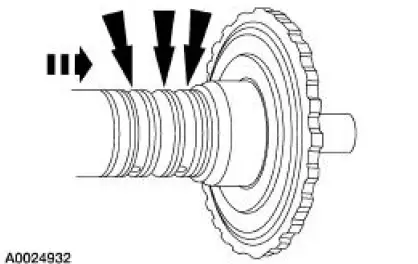
Remove the ring gear snap ring.
2. Separate the ring gea ...
 Torque Converter (Disassembly and Assembly of Subassemblies)
1. A new or remanufactured torque converter must be installed if one or more
of the following
statements is true:
A torque converter malfunction has been determined based on complete
diagnostic
...
Other materials:
Exhaust Manifold RH
Removal and Installation
1. Disconnect the battery negative cable. For additional information,
refer to Section.
2. Remove the air cleaner outlet pipe. For additional information, refer to
Section.
3. Disconnect the differential pressure feedback exha ...
Entertainment System - General Information
Audio System (Diagnosis and Testing)
Refer to Wiring Diagrams Cell 130 , Radio for schematic and connector
information.
Special Tool(s)
73III Automotive Meter
105-R0057 or equivalent
Inspection and Verification
1. Verify the customer con ...
Climate Control System (Description and Operation)
WARNING: To avoid accidental deployment and possible injury, the air
bag system
backup power supply must be depleted before repairing any climate control
components. To
deplete the backup power supply, disconnect the battery ground cable and wait
one minute ...
