Ford Mustang (1999-2004) Service Manual: Push Rods - Inspection
1. CAUTION: Do not attempt to straighten push rods.
Check the ends of the push rods for nicks, grooves, roughness or excessive wear. Install new push rods as necessary. Refer to the appropriate section in Group 303 for the procedure.
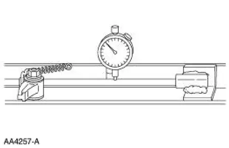
- The push rods can be checked for straightness while they are installed in the engine by rotating them with the valve closed.
- They also can be checked using a Dial Indicator with Bracketry.
2. If the push rod is bent beyond specifications, install a new push rod. Refer to the appropriate section in Group 303 for the procedure.
Camshaft Journal -Diameter
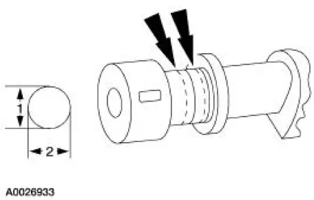
1. Measure each camshaft journal diameter in two directions.
- If out of specification, install new components as necessary. Refer to the appropriate section in Group 303 for the procedure.
Camshaft Journal -Clearance, Push Rod Engines, Micrometer Method
1. NOTE: The camshaft journals must meet specifications before checking camshaft journal clearance.
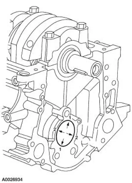
Measure each camshaft bearing (6261) in two directions.
- Subtract the camshaft journal diameter from the camshaft bearing diameter.
 Rocker Arms - Inspection
CAUTION: Do not attempt to true surfaces by grinding. Check the
rocker arm pad, side
rails and seat for excessive wear, cracks, nicks or burrs. Check the rocker
arm seat bolt for
stripped or bro ...
 Camshaft Journal - Clearance, Plastigage Method
Special Tool(s)
Plastigage
303-D031 (D81L-6002-B) or
equivalent
NOTE: The camshaft journals must meet specifications before checking
camshaft journal clearance.
1. Remove the camsh ...
Other materials:
Engine
A modular engine is built around four modules:
the intake module
the cylinder head module (RH)
the cylinder head module (LH)
the lower engine module
While not all repairs can take advantage of the modular concept, mos ...
Differential Housing Cover
Removal
1. Raise and support the vehicle.
2. NOTE: Empty the lubricant into a clean container for reuse.
Remove the differential housing cover (4033).
1. Remove the 10 bolts and drain the lubricant from the differential
housing (4010).
2. Remove the d ...
Input Shaft and Bearing
Special Tool(s)
Input Shaft Seal Replacer
308-220 (T94P-7025-AH)
Pinion Bearing Cone Remover
205-D002 (D79L-4621-A) or
Equivalent
Disassembly
1. Using the special tool and a press, remove the input bearing (7025).
2. Remove t ...
