Ford Mustang (1999-2004) Service Manual: Removal
1. Remove the A/C compressor (19703). For additional information, refer to Air Conditioning (A/C) Compressor-3.8L or Air Conditioning (A/C) Compressor-4.6L in this section.
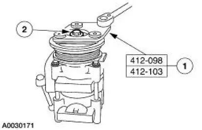
2. Remove the bolt.
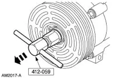
1. Hold the A/C disc and hub assembly (19D786) with the special tool.
2. Remove the bolt.
3. Remove the A/C disc and hub assembly and spacer (19D648).
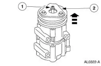
1. Thread an 8 x 1.25 mm (0.05 in) bolt into the A/C disc and hub assembly to force it from the compressor shaft.
2. Lift the A/C disc and hub assembly and spacer from the compressor shaft.
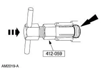
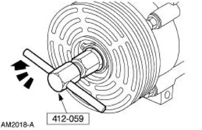
4. Using the special tool, remove the shaft seal felt from the nose of the A/C compressor.
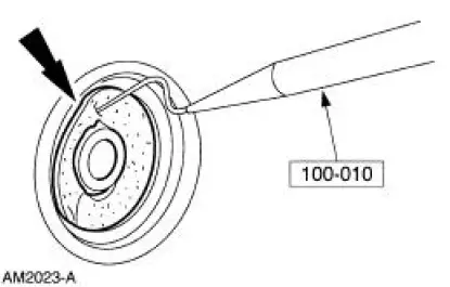
5. Clean the compressor nose area.
6. Insert the tip of the special tool into one of the snap ring eyes.
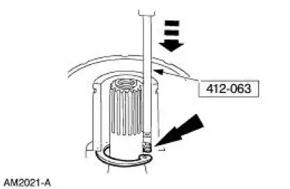
7. Rotate the special tool to position the tool tip and the snap ring eye closest to the A/C compressor shaft.
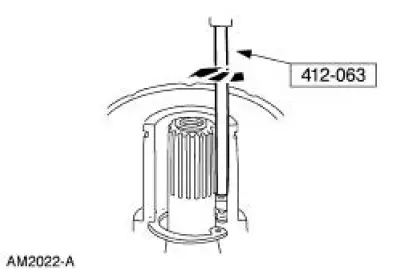
8. Pull the special tool up quickly while keeping the tool shaft against the side of the nose opening and remove the snap ring.
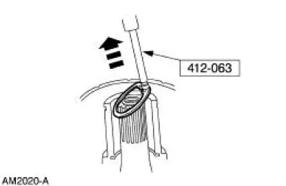
9. Engage the special tool into the inside diameter of the shaft seal.
10. Turn the tool handle clockwise to expand the tool tip inside the shaft seal.
11. Pull the seal from the A/C compressor.
 Air Conditioning (A/C) Compressor Shaft Seal
Special Tool(s)
Holding Fixture, Compressor
Clutch (3.8L vehicles)
412-098 (T94P-19703-AH)
Holding Fixture, Compressor
Clutch (4.6L vehicles)
412-103 (T95L-19703-AH)
...
 Installation
1. CAUTION: To prevent refrigerant system contamination, do not allow
dirt or other
foreign materials to enter the A/C compressor.
Clean the A/C compressor nose area.
2. Place the shaft seal on the s ...
Other materials:
Fittings - Vapor Tube
Disconnect
1. WARNING: The evaporative emission system contains fuel vapor and
condensed
fuel vapor. Although not present in large quantities, it still presents the
danger of
explosion or fire. Disconnect the battery ground cable from the battery to
minimiz ...
Differential Case and Ring Gear
Special Tool(s)
2-Jaw Puller
205-D072 (D97L-4221-A) or
equivalent
Installer, Differential Side
Bearing
205-009 (T57L-4221-A1)
Step Plate
205-D016 (D80L-630-5) or
equivalent
...
Engine (Disassembly)
Special Tool(s)
Service Set, Camshaft
303-017 (T65L-6250-A)
Remover, Crankshaft Vibration
Damper
303-009 (T58P-6316-D)
Lifting Bracket Set, Engine
303-D095 (D94L-6001-A) or
equivalent
Remover, Power Stee ...
