Ford Mustang (1999-2004) Service Manual: Removal
NOTE: The convertible top hydraulic components are removed from the vehicle as an assembly. The hydraulic components are individually repaired and the system must be bled before being installed into the vehicle.
Hydraulic system
1. Unlatch the convertible top.
2. Remove the rear quarter trim panel. For additional information, refer to Section.
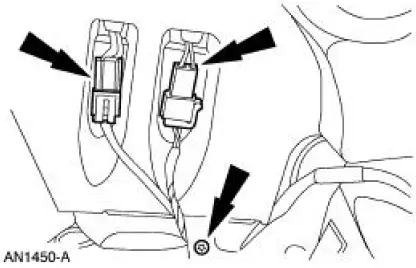
3. NOTE: This step applies to vehicles equipped with the Mach sound system.
Remove the screw and disconnect the electrical connectors.
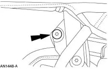
4. Remove the screws.
5. Remove the speakers.
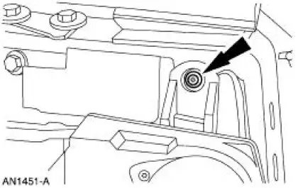
6. Remove the two cylinder rod mounting bolts.
7. Fully lower the lift cylinders.
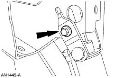
8. Remove the nuts and the lift cylinders.
9. Release the hydraulic line retainers on each side.
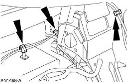
10. Disconnect the motor electrical connector.
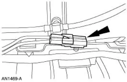
11. Pull up on the motor to release the rubber retainers.
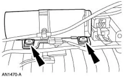
12. Remove the motor and cylinders as an assembly.
Lift cylinder
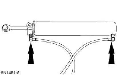
13. NOTE: Prior to their removal, mark the upper and lower hydraulic lines to insure correct installation on the new cylinder.
Remove the hydraulic lines from the cylinder.
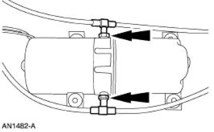
Motor assembly
14. NOTE: Prior to removal, mark the hydraulic lines to insure correct installation of the motor assembly.
Remove the hydraulic lines from the motor assembly.

 Installation
Lift cylinder
1. NOTE: Be sure that each fitting is installed in the correct position on
the folding top hydraulic
component.
NOTE: Make sure that the tetra seal is installed in the bottom of each of ...
Other materials:
Resistor
Removal
1. Disconnect the connector.
2. Remove the screws.
3. Remove the resistor.
Installation
1. To install, reverse the removal procedure. ...
Driveline Angle Inspection
Special Tool(s)
Anglemaster II Driveline
Inclinometer
164-R2402 or equivalent
NOTE: An incorrect driveline angle can cause a vibration or shudder.
1. Check the vehicle for evidence or overload or sagging. Check for specified
air pressures
in ...
Floor Console
Removal and Installation
All vehicles
1. Disconnect the battery ground cable. For additional information,
refer to Section .
2. Apply the parking brake.
Vehicles with automatic transmission
3. Place the selector lever in the 1 position.
Vehicle ...
