Ford Mustang (1999-2004) Service Manual: Removal
CAUTION: Suspension fasteners are critical parts because they affect performance of vital components and systems and their failure can result in major service expense. A new part with the same part number must be installed if installation becomes necessary. If substitution is necessary, the part must be of the same finish and property class. Torque values must be used as specified during reassembly to make sure of correct retention of these parts.
1. Raise the vehicle on a hoist.
2. Support the No. 1 crossmember with a jack stand.
3. Remove both wheel and tire assemblies.
4. Remove both mufflers.
5. Remove the driveshaft.
6. Disconnect the parking brake cable and conduits from the parking brake levers.
7. Remove the clip and disconnect the parking brake cable and conduits from the rear brake calipers.
8. Disconnect the parking brake cable and conduits from the knuckles (5A968/5A969).
9. Remove the bolts and the parking brake cable brackets.
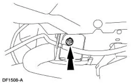
10. Remove the bolts and the rear brake lines.
11. Remove the bolts and the ABS sensors.
12. Unclip the ABS sensor wires from the subframe.
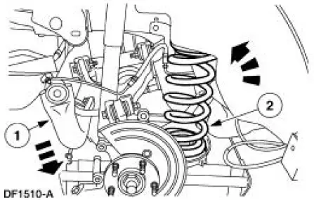
13. Support the lower suspension arm and bushings (5A649) with jack stands.
14. Remove the nuts, bolts and disconnect the shock absorbers (18125) from the lower suspension arm and bushings. Discard the bolts and nuts.
15. Lower the lower suspension arm and bushings and remove the jack stands.
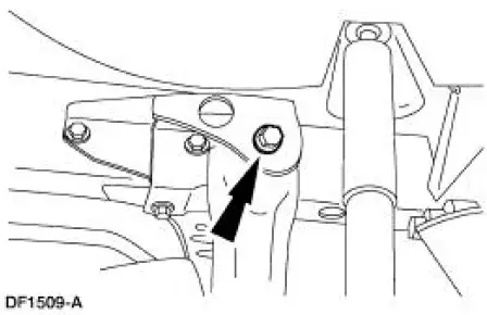
16. Support the rear subframe using the special tool 014-00765.
17. Remove and discard the nuts from the subframe front bolts.
18. Remove and discard the subframe rear bolts.
19. Remove the springs (5560).
1. Carefully lower the subframe with the special tool 014-00765, allowing the subframe to pivot on the front bolts.
2. Remove the springs and the spring insulators (5536).
 Spring - Cobra
Special Tool(s)
Rotunda Powertrain Lift
014-00765 or Equivalent
...
 Installation
1. NOTE: Inspect the spring insulators for wear or damage. Install new
spring insulators if
necessary.
Make sure the spring insulators are correctly installed on the springs.
2. Install the spring ...
Other materials:
Front passenger sensing system
WARNING: Even with Advanced Restraints Systems, children 12
and under should be properly restrained in a rear seating
position. Failure to follow this could seriously increase the risk of injury
or death.
WARNING: Sitting improperly out of position or with the ...
Wheel Hub or Axle Flange Face Runout
NOTE: If the axle shaft assembly is removed, check runout of the shaft
itself. The forged (unmachined)
part of the shaft is allowed to have as much as 3.0 mm (0.120 inch) runout. This
alone will not cause a
vibration condition.
1. Position the special tool ...
Inspection and Verification
1. Verify the customer concern by operating the engine to duplicate the
condition.
2. Visually inspect for obvious signs of mechanical damage. Refer to the
following chart.
Visual Inspection Chart
Mechanical
Engine coolant leaks
...
