Ford Mustang (1999-2004) Service Manual: Installation
All vehicles
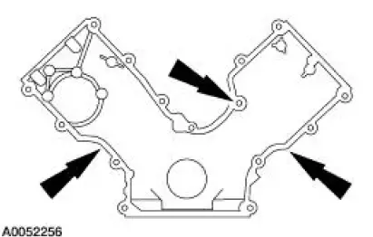
1. Position the engine front cover gasket on the engine front cover.
2. NOTE: If the engine front cover is not secured within four minutes, the sealant must be removed and the sealing area cleaned with metal surface cleaner. Allow to dry until there is no sign of wetness, or four minutes, whichever is longer. Failure to follow this procedure can cause future oil leakage.
Apply the silicone gasket and sealant along the cylinder head-to-cylinder block surface and the oil pan-to-cylinder block surface.
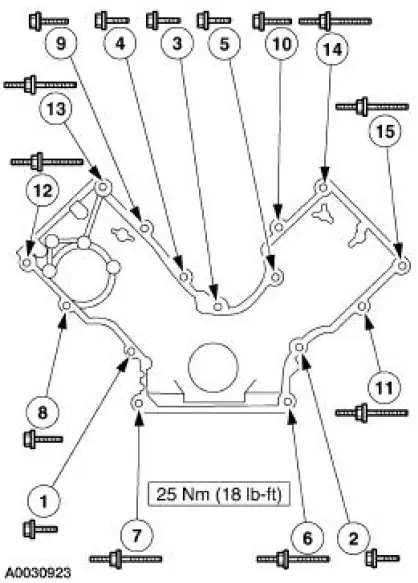
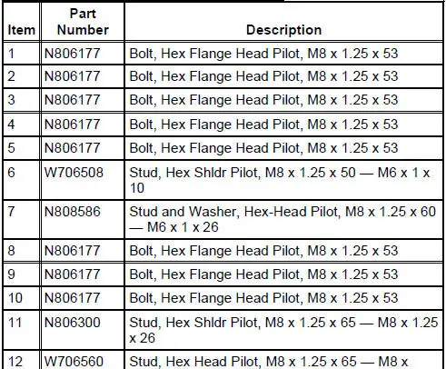
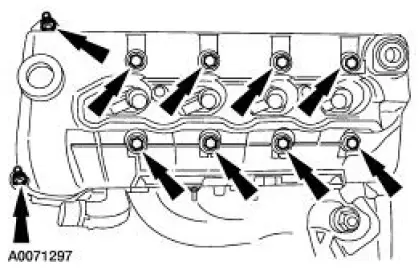
3. Install the engine front cover and tighten the bolts and studs in sequence shown.
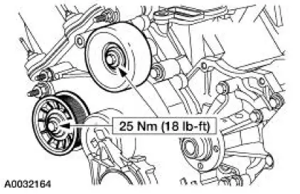
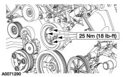
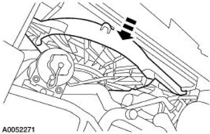
4. Install the idler pulleys.
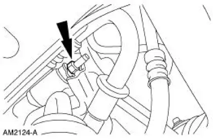
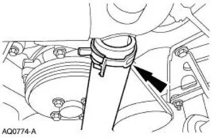
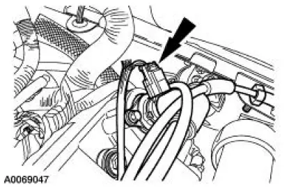
5. Connect the camshaft position (CMP) sensor electrical connector.
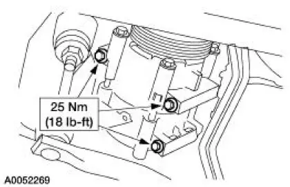
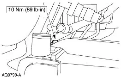
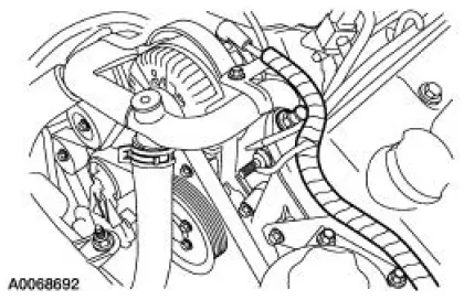
6. Position the power steering reservoir and bracket assembly and install the bolts.
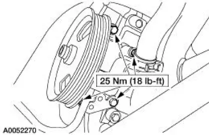
7. Install the coolant pump pulley and the bolts.
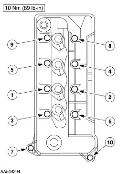
8. Install the LH valve cover and loosely install the bolts.
9. Tighten the LH valve cover bolts in the sequence shown.
10. Raise and support the vehicle. For additional information, refer to Section.
Manual transmission vehicles
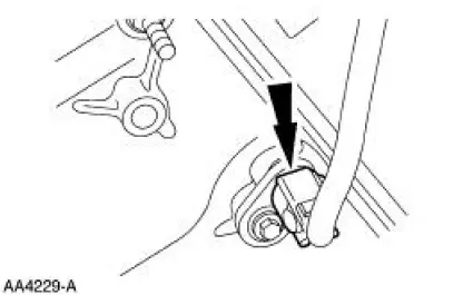
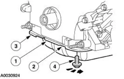
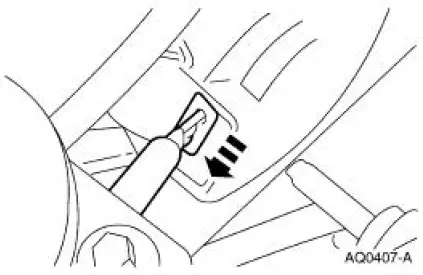
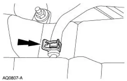
11. Connect the clutch release cable to the clutch release fork.
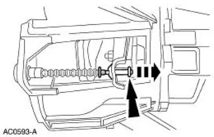
12. Install the clutch release cable shield and the bolt.
All vehicles
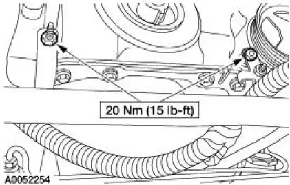
13. Loosely install the four oil pan bolts. Tighten the bolts in three stages, and in the sequence shown.
1. Stage 1: Tighten the bolts to 2 Nm (18 lb-in).
2. Stage 2: Tighten the bolts to 20 Nm (15 lb-ft).
3. Stage 3: Tighten the bolts an additional 90 degrees (1/4 turn).
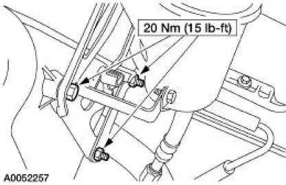
14. Position the wiring harness and install the nuts.
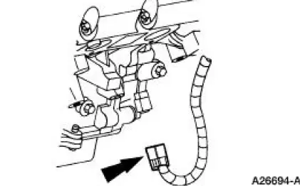
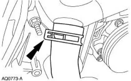
15. Connect the crankshaft position (CKP) sensor electrical connector.
16. Position the A/C compressor, A/C muffler, and the hose. Install the bolts.
17. Install the A/C muffler bracket nut.
18. Position the power steering pump and install the bolts.
19. Install the crankshaft front oil seal. For additional information, refer to Crankshaft Front Oil Seal in this section.
20. Position the cooling fan and shroud in the installed position.
21. Install the RH cooling fan bolt.
22. Install the LH cooling fan bolt.
23. Attach the cooling fan wiring harness to the fan shroud.
24. Connect the cooling fan electrical connector.
25. Connect the lower radiator hose to the bypass tube.
26. Connect the upper radiator hose to the bypass tube.
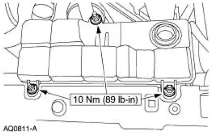
27. Install the degas bottle and the nuts.
28. Connect the degas bottle return hose.
29. Connect the degas bottle vent hose.
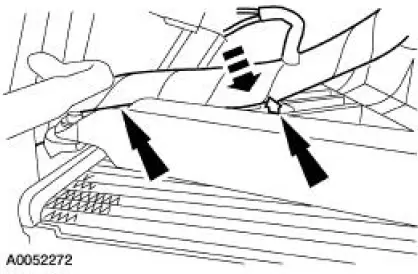
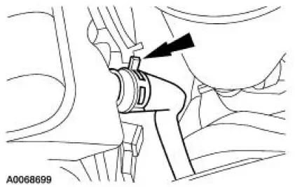
30. Connect the wiring harness anchor to the valve cover.
31. Install the positive crankcase ventilation (PCV) valve hose and connect the electrical connector.
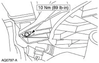
32. Position the oil level indicator tube and install the bolt.
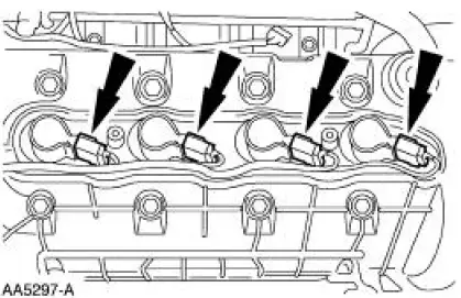
33. Install the LH ignition coils.
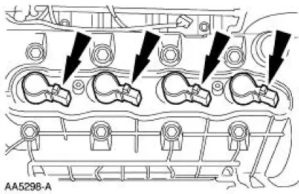
34. Connect the LH ignition coil electrical connectors.
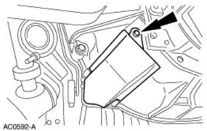
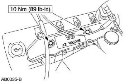
35. Install the LH coil cover and install the bolts.
Manual transmission vehicles
36. Install the clutch release cable screws.
All vehicles
37. Install the RH valve cover. For additional information, refer to Valve Cover RH in this section.
38. Install the Hydro-Boost brake booster. For additional information, refer to Section.
39. Install the air intake scoop bracket. For additional information, refer to Section.
40. Fill the crankcase with clean engine oil.
 Removal
All vehicles
1. Remove the air intake scoop bracket. For additional information, refer to
Section.
2. Remove the RH valve cover. For additional information, refer to Valve Cover
RH in this section. ...
 Timing Drive Components
Special Tool(s)
Holding Tool, Crankshaft
303-448 (T93P-6303-A)
...
Other materials:
Master Cylinder Priming - 4.6L
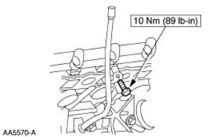
1. CAUTION: Use only bleed screws on the engine side of the
brake master cylinder
(2140). The hydro-boost bleed screw, located near the dash on the
hydro-booster
casting, is for the booster cavity filled with power steering fluid, not
brake fluid. ...
Ignition Coil-On-Plug
Material
Item
Specification
Silicone Brake Caliper Grease
and Dielectric Compound
D7AZ-19A331-A or equivalent
ESE-M1C171-
A
Removal and Installation
1. Disconnect the battery ground cable. For additional information, refer
to Section ...
Engine oil check
Note: Check the level before starting the engine.
Note: Make sure that the level is between the MIN and MAX marks.
1. Make sure that your vehicle is on level ground.
2. Turn the engine off and wait 10 minutes for the oil to drain into the
oil pan.
3. Remove ...
