Ford Mustang (1999-2004) Service Manual: Removal
1. Disconnect the battery ground cable (14301).
2. Remove the air cleaner outlet tube (9B659).
3. Remove the radiator sight shield (8C291).
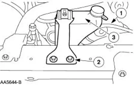
4. Remove the coolant recovery reservoir (8A080).
1. Disconnect the hose.
2. Remove the bolts.
3. Remove the coolant recovery reservoir.
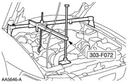
5. Install the special tool.
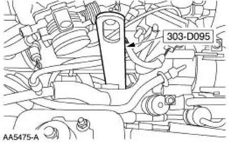
6. Install the special tool.
7. Install the special tool.
8. Raise the vehicle on a hoist.
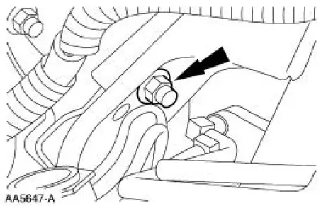
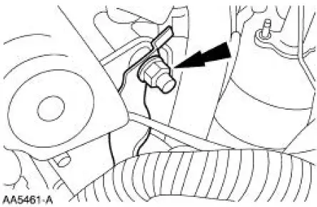
9. Remove the LH engine mount nut.
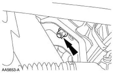
10. Remove the RH engine mount nut.
11. Lower the vehicle.
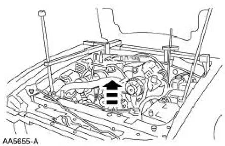
12. Raise the engine.
13. Raise the vehicle on a hoist.
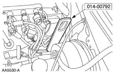
14. Position the bracket aside.
- Remove the nut.
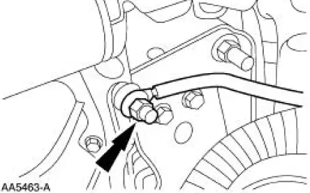
15. Disconnect the engine ground strap.
- Remove the nut.
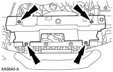
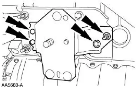
16. Remove the LH engine insulator (6038).
- Remove the bolts.
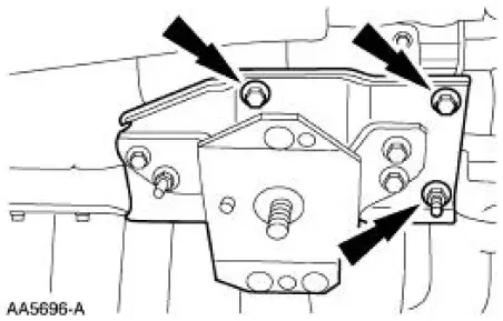
17. Remove the RH engine insulator.
- Remove the bolts.
- Remove the nuts.
 Engine Support Insulators
Special Tool(s)
3 Bar Engine Support Kit
303-F072
Engine Lift Bracket Set
303-D095 (D94L-6001-A) or
equivalent
...
 Installation
1. Install the RH engine insulator.
Install the nuts.
Install the bolts.
2. Install the LH engine insulator.
3. Connect the engine ground strap.
4. Install the bracket.
5. Lower the ve ...
Other materials:
Engine Ignition (Description and Operation)
Eight separate ignition coils (12029):
are mounted directly above each spark plug (12405).
are controlled by the powertrain control module (PCM) for correct
firing sequence.
The spark plug:
changes the high voltage pulse into a spark which igni ...
Information contained on the tire sidewall
Both U.S. and Canada Federal regulations require tire manufacturers
to place standardized information on the sidewall of all tires. This
information identifies and describes the fundamental characteristics of
the tire and also provides a U.S. DOT Tire Identifi ...
Navigation system
Your navigation system allows you to set a destination by using your
touchscreen or voice commands.
The navigation system contains map coverage for the United States,
Puerto Rico and U.S. Virgin Islands, Canada and Mexico.
Disclaimer
A disclaimer appears onc ...
