Ford Mustang (1999-2004) Service Manual: Transmission (Disassembly)
Special Tool(s)
|
|
Holding Fixture, Transmission 307-003 (T57L-500-B) |
|
|
Puller, Bearing 205-D064 (D84L-1123-A) |
|
|
2 or 3 Jaw Puller 205-D027 (D80L-1013-A) |
|
|
Remover, Mainshaft Bearing 308-058 (T77J-7025-H) |
|
|
Remover/Installer, Bearing Tube 308-025 (T75L-7025-C) |
|
|
Removal Screw, Bearing Tube 308-092 (T84T-7025-B) |
Disassembly
NOTE: During disassembly, if any roll pins, retaining rings or bearings are removed, install new components. Install bearings and bearing cups as a set only.
1. WARNING: Make sure protective eye wear is in place.
Clean the transmission exterior with solvent and dry with compressed air. During disassembly, clean all components with solvent and dry with compressed air.
2. Remove the clutch release hub and bearing and the clutch release lever.
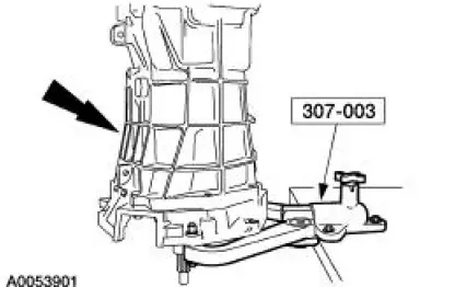
3. Attach the transmission to the special tool.
4. Rotate the transmission to a horizontal position.
5. NOTE: Position a drain pan under the transmission.
If the transmission was not drained during removal, drain the transmission.
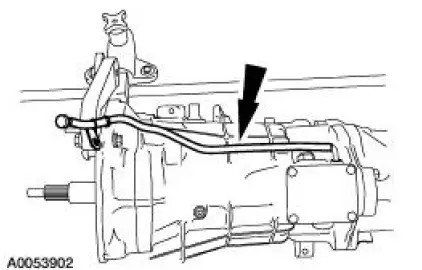
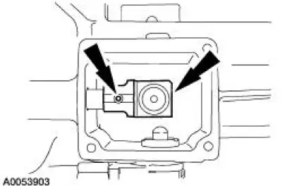
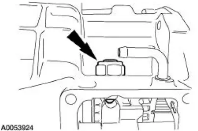
6. Remove the vent hose.
7. NOTE: Position the gearshift lever in third/fourth neutral position.
Using a 5/32-inch drift and a hammer, drive the roll pin downward, then remove the rear offset shift lever.
- Inspect the rear offset shift lever for wear or damage. Install a new lever as necessary.
- Discard the roll pin.
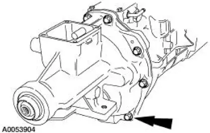
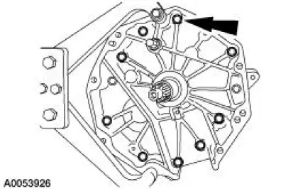
8. Remove the eight bolts and carefully separate the extension housing from the transmission.
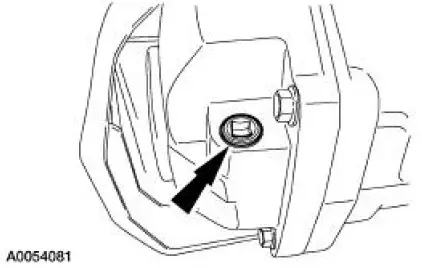
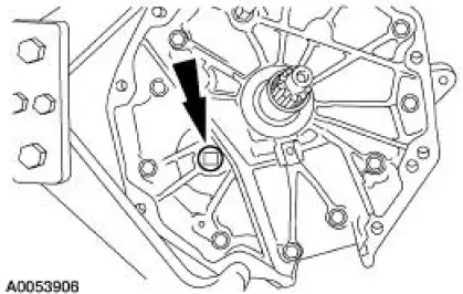
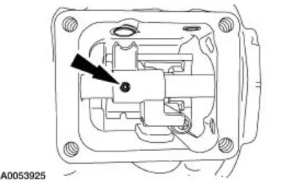
9. Remove the plug from the transmission adapter plate.
10. NOTE: Rotate the transmission to a vertical position.
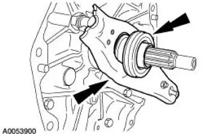
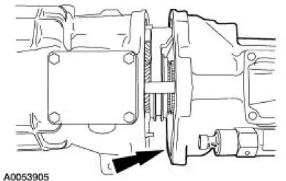
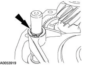
Remove the shipping seal.
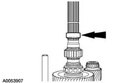
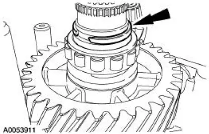
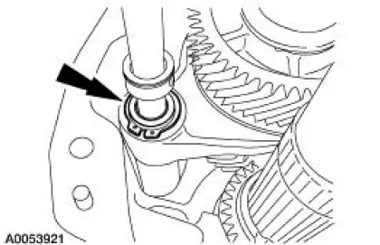
11. Remove the output shaft speed (OSS) sensor tone wheel retaining ring.
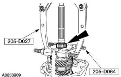
12. Using the special tools, remove the OSS sensor tone wheel.
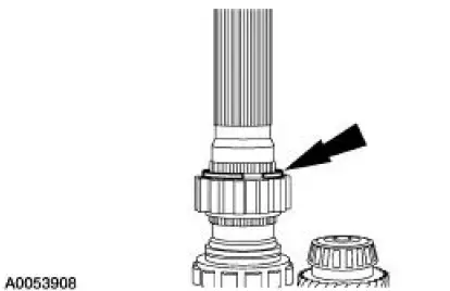
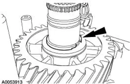
13. Remove and discard the OSS sensor tone wheel lower retaining ring.
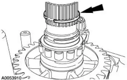
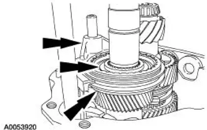
14. Remove and discard the rear mainshaft roller bearing snap ring.
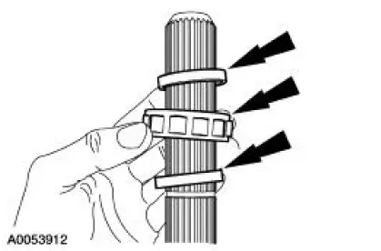
15. Remove the upper spacer, the rear mainshaft roller bearing and the lower spacer.
- Inspect the rear mainshaft roller bearing for wear or damage. Install a new bearing as necessary.
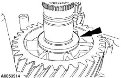
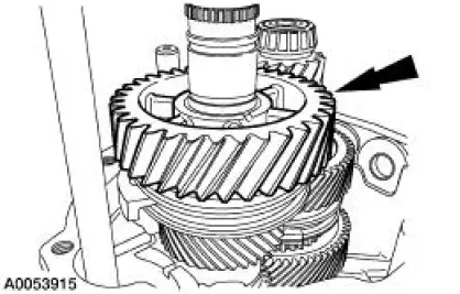
16. Remove and discard the reverse gear snap ring.
17. Remove the reverse gear thrust washer.
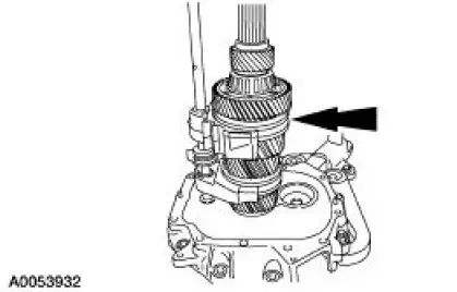
18. Remove the reverse gear.
- Inspect reverse gear for wear or damage. Install a new gear as necessary.
19. Remove the wave washer from the reverse gear.
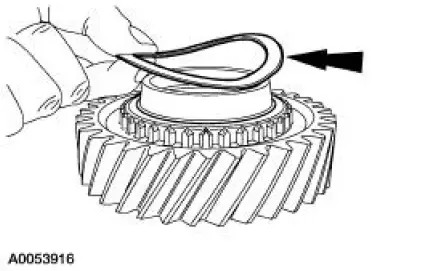
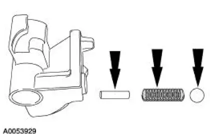
20. Remove the reverse gear needle bearing and the reverse gear synchronizer blocking ring.
- Inspect the needle bearing for wear or damage. Install a new bearing as necessary.
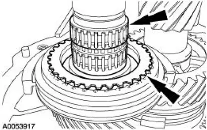
21. Remove the reverse gear synchronizer snap ring.
22. Remove the reverse shift fork snap ring.
23. Remove the reverse shift fork, the reverse synchronizer and the thrust washer as an assembly.
24. Inspect the synchronizer for the following:
- Check for worn, nicked or broken teeth. Install a new synchronizer as necessary.
- Check keys for wear or distortion. Check the springs for distortion. Install a new synchronizer as necessary.
25. Inspect the synchronizer blocking ring for the following:
- Check for wear or damage. Install a new synchronizer blocking ring as necessary.
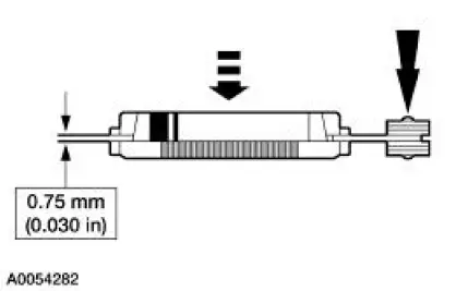
- Check the clearance between the synchronizer blocking ring and the gear.
- Position the blocking ring onto the gear. Make sure the correct blocking ring is measured with the correct gear and that the blocking ring is fully seated on the gear.
- Insert a feeler gauge and measure the clearance, while applying pressure and rotating the blocking ring. The measurement should be the same around the entire circumference. If the clearance is less than 0.75 mm (0.030 in), install new blocking ring.
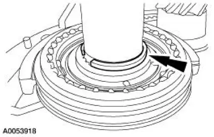
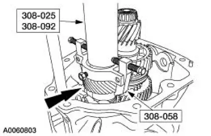
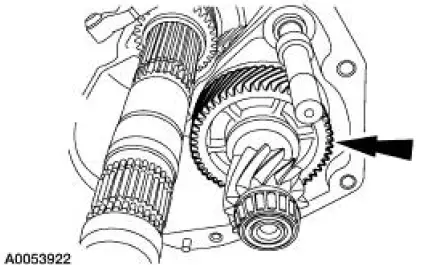
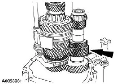
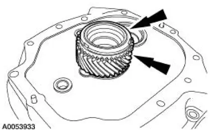
26. Using the special tools, remove the fifth/sixth driven gear.
27. Remove the fifth/sixth shift fork snap ring.
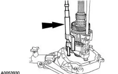
28. Rotate the transmission to the horizontal position, then remove the countershaft extension as an assembly.
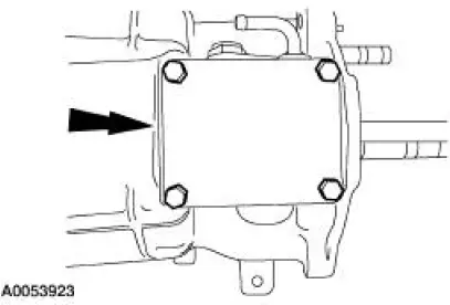
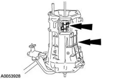
29. Remove the shift detent cover.
30. Remove the shift detent assembly.
31. Using a 5/32-inch drift and a hammer, drive the roll pin downward.
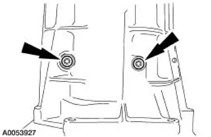
32. Remove nine of the adapter-to-transmission case bolts.
33. NOTE: Rotate the transmission to a vertical position.
Remove the shift lever guide bolts.
34. Remove the two remaining adapter-to-transmission case bolts, then remove the transmission case and the front offset lever.
- Slide the transmission case upward, off the mainshaft and shift rails. Hold the offset lever against the guide plate to prevent the release of the dent ball and spring.
35. Remove the dent ball, spring and roll pin from the front offset lever.
36. Rotate the fifth/sixth and reverse shift levers from the shift interlock plate, then remove the fifth/sixth and reverse shift rail assembly.
37. Lift up the mainshaft, then remove the countershaft.
38. Remove the mainshaft and shift rail as an assembly. Separate the shift rail assembly from the mainshaft on the work bench.
39. Remove the input shaft and fourth gear synchronizer blocking ring.
40. Remove the countershaft bearing cup and the countershaft shim.
- Inspect the cup for wear or damage. Install a new cup and bearing as necessary.
- Inspect the cup bore for wear, scratches or grooves. Install a new transmission adapter plate as necessary.
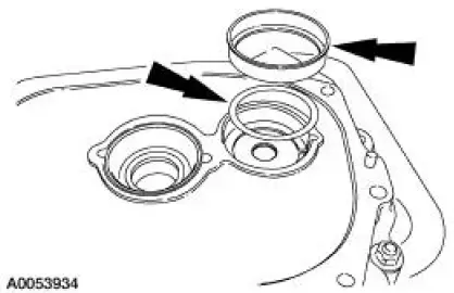
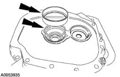
41. Remove the input shaft bearing cup and input shaft shim.
- Inspect the cup for wear or damage. Install a new cup and bearing as necessary.
- Inspect the cup bore for wear, scratches or grooves. Install a new transmission adapter plate as necessary.
42. Remove and discard the input shaft seal.
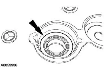
43. WARNING: Make sure protective eye wear is in place.
Clean the transmission adapter plate with solvent and dry with compressed air. Inspect the adapter plate for cracks. Clean and check the sealing surface for nicks or scratches.
- If the adapter plate is cracked, install a new plate. If the sealing surface has nicks or scratches, use a soft stone or crocus cloth to remove.
 Transmission (Removal)
1. Remove the gearshift lever knob.
2. Remove the console panel gearshift plate. Disconnect the cigar lighter
electrical connector, then
lift the gearshift lever boot over the gearshift lever.
3. ...
 Input Shaft and Bearing
Special Tool(s)
Plate, Bearing/Oil Seal
205-090 (T75L-1165-B)
Puller, Bearing
205-D064 (D84L-1123-A)
Installer, Drive Pinion Bearing
Cone
205-004 (T53T-4621- ...
Other materials:
Spring Codes
The spring code portion of the vehicle certification (VC) label identifies
both the front and rear springs.
The first letter/number indicates the front spring code. The second
letter/number indicates the rear
spring code.
Front springs - base part numbe ...
Engine - 4.6L (2V)
General Specifications
a - With installation of a new filter.
b - Distance front edge of bearing is installed below front face of cylinder
block.
c - Time necessary for plunger to leak down 1.6 mm of travel with 222 N force
and leak down fluid in
tap ...
Removal
1. CAUTION: The vehicle must be on level ground and at curb height.
Mark the rear shock absorbers relative to their protective sleeve.
During installation, raise the suspension to this reference mark before
tightening the
suspension component fasteners.
...
