Ford Mustang (1999-2004) Service Manual: Removal
1. Remove the upper intake manifold. For additional information, refer to Intake Manifold-Upper in this section.
2. Disconnect the fuel line. For additional information, refer to Section.
3. Remove the coolant by-pass tube. For additional information, refer to Section.
4. Remove the generator. For additional information, refer to Section.
5. Disconnect the electrical connector and the vacuum line from the fuel pressure sensor.
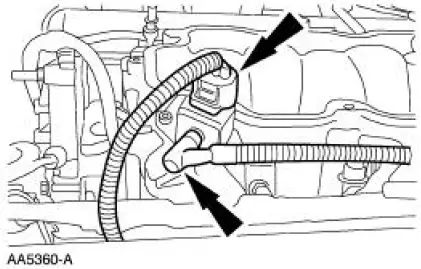
6. Disconnect the eight fuel injector electrical connectors.
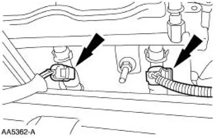
7. Separate the fuel charging wiring harness from the fuel injection supply manifold studs in three places.
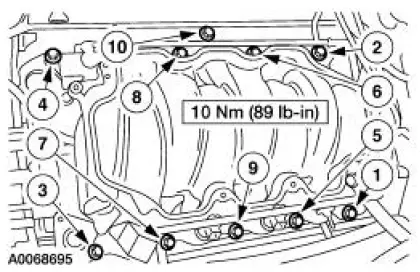
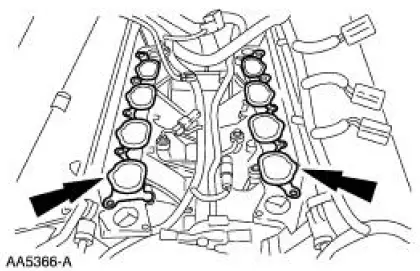
8. Remove the ten bolts in the sequence shown and raise the lower intake manifold slightly.
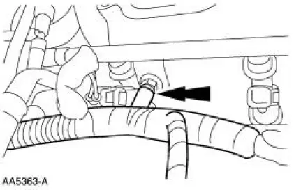
9. Disconnect the fuel charging wiring harness from the rear of the lower intake manifold and remove the manifold.
10. Remove the intake manifold gaskets.
- Clean and inspect the sealing surfaces.
 Intake Manifold - Lower
Material
Item
Specification
Metal Surface Cleaner
F4AZ-19A536-RA or equivalent
WSE-M5B392-A
...
 Installation
1. Install the lower intake manifold gaskets.
2. Connect the fuel charging wiring harness to the rear of the lower intake
manifold and install the
manifold.
3. Install the intake manifold fastener ...
Other materials:
Reversing Lamps
Refer to Wiring Diagrams Cell 93 , Backup Lamps for schematic and
connector information.
Special Tool(s)
73III Automotive Meter or
equivalent
105-R0057
Inspection and Verification
1. Verify the customer concern by operating the reversing l ...
Towing the vehicle on four whe
Emergency Towing
If your vehicle becomes inoperable (without access to wheel dollies,
car-hauling trailer, or flatbed transport vehicle), it can be flat-towed
(all wheels on the ground, regardless of the powertrain and transmission
configuration) under the fol ...
Installation
1. Position the side rail and install the bolts.
2. NOTE: Tighten the bottom bolt first.
Connect the mounting bracket and install the bolts.
3. NOTE: Line up the marks in the number four bow.
Tighten the bolt.
4. Connect the number two and number three ...
