Ford Mustang (1999-2004) Service Manual: Installation
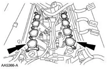
1. Install the lower intake manifold gaskets.
2. Connect the fuel charging wiring harness to the rear of the lower intake manifold and install the manifold.
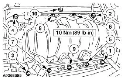
3. Install the intake manifold fasteners and tighten in the sequence shown.
4. Position the fuel charging wiring harness and connect it to the fuel injection supply manifold in three places.
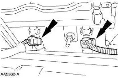
5. Connect the eight fuel injector electrical connectors.
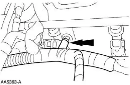
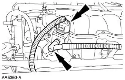
6. Connect the electrical connector and the vacuum line to the fuel pressure sensor.
7. Install the generator. For additional information, refer to Section .
8. Install the coolant bypass tube. For additional information, refer to Section.
9. Connect the fuel line. For additional information, refer to Section.
10. Install the upper intake manifold. For additional information, refer to Intake Manifold-Upper in this section.
 Removal
1. Remove the upper intake manifold. For additional information, refer to
Intake Manifold-Upper
in this section.
2. Disconnect the fuel line. For additional information, refer to Section.
3. Remove ...
 Valve Cover RH
Material
Item
Specification
Metal Surface Cleaner
F4AZ-19A536-RA or equivalent
WSE-M5B392-
A
Silicone Gasket and Sealant
F7AZ-19554-EA or equivalent
WSE-M4G323-
A4
...
Other materials:
Transmission (DISASSEMBLY)
Special Tool(s)
Slide Hammer
100-001 (T50T-100-A)
Holding Fixture, Transmission
307-003 (T57L-500-B)
Slide Hammer
307-005 (T59L-100-B)
Remover, Transmission Fluid
Seal
307-048 (T74P-77248-A)
...
Interior luggage compartment release
WARNING: Keep vehicle doors and luggage compartment locked
and keep keys and remote transmitters out of a child’s reach.
Unsupervised children could lock themselves in the trunk and risk
injury. Children should be taught not to play in vehicles.
WARNING: Do ...
Universal Garage Door Opener (If Equipped)
UNIVERSAL GARAGE DOOR OPENER
The appearance of your vehicle’s universal garage door opener will
vary according to your option package. Before programing, make sure
you identify which transmitter you have by comparing it to the graphics
below.
HomeLink®
Ca ...
