Ford Mustang (1999-2004) Service Manual: Removal
Both mounts
1. Disconnect the battery ground cable. For additional information, refer to Section.
2. Remove the coolant bypass tube. For additional information, refer to Section.
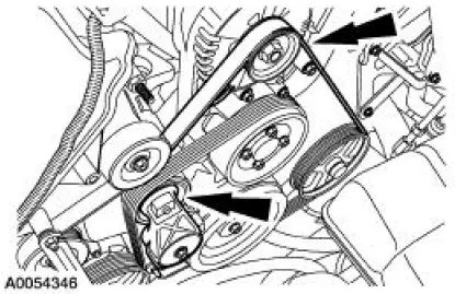
3. Rotate the drive belt tensioner clockwise and detach the drive belt from the generator pulley.
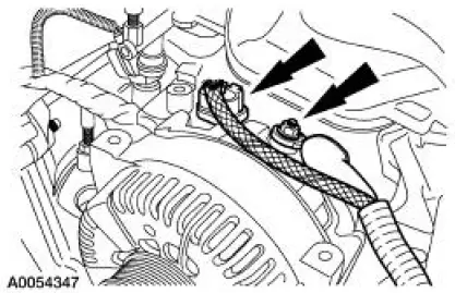
4. Disconnect the generator electrical connections.
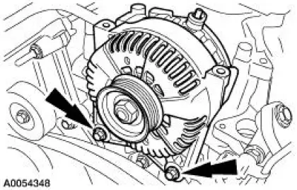
5. Remove the bolts and the generator.
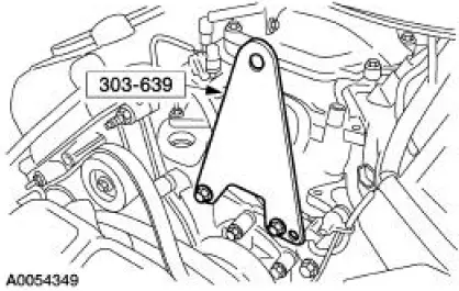
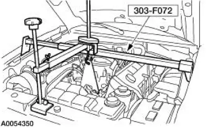
6. Install the special tool.
7. Using the special tool, support the engine.
8. Remove the front springs. For additional information, refer to Section.
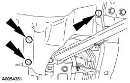
9. NOTE: RH shown, LH similar.
Remove the six splash-shield pushpins.
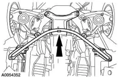
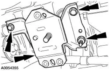
10. Remove the 13 bolts and the cross-brace support.
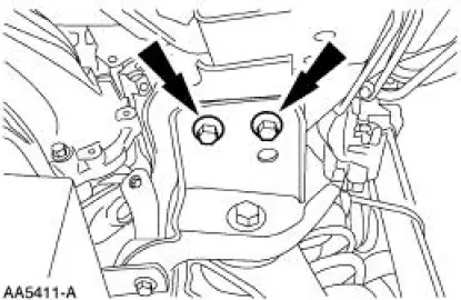
11. NOTE: RH shown, LH similar.
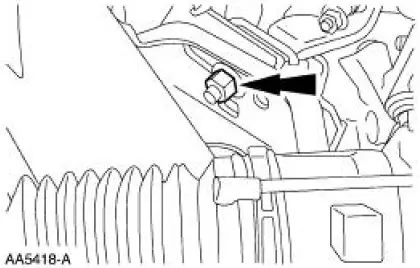
Remove the two engine mount nuts.
12. Using two jackstands, support the subframe.
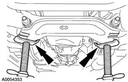
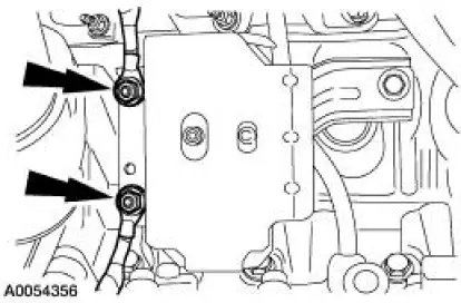
13. NOTE: Mark the bolts and the crossmember location for assembly reference.
NOTE: RH shown, LH similar.
Remove the four bolts.
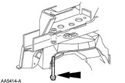
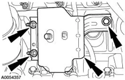
14. NOTE: RH shown, LH similar.
Remove the four bolts.
15. Using the jackstands, lower the front subframe.
RH mount
16. Remove the nut and detach the wiring harness.
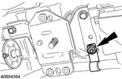
17. Remove the bolts, the studbolt and the engine mount.
LH mount
18. Remove the nuts and detach the ground cables.
19. Remove the bolt, the studbolts and the engine mount.
 Engine Mount
Special Tool(s)
Support Bracket, Engine
303-639
3-Bar Engine Support Kit
303-F072
Alignment Tool, Subframe
502-004
...
 Installation
LH mount
1. Position the engine mount and install the bolt and studbolts.
2. Attach the ground cables and install the nuts.
RH mount
3. Position the engine mount and install the bolts and studbolt ...
Other materials:
Hill start assist
WARNING: The hill start assist feature does not replace the
parking brake. When you leave the vehicle, always apply the
parking brake and shift the transmission into position P for automatic
transmission or position 1 for manual transmissions.
WARNING: You mus ...
Pinpoint Test O: DTC B1870 - Air Bag Indicator Shorted to Battery
Normal Operation
The air bag indicator is designed to illuminate for 6 (+/-2) seconds
when the ignition switch is turned to
the RUN position. This initial 6 seconds of illumination is considered
normal operation and is called
proveout of the air ba ...
Wheel
Removal and Installation
1. Disconnect the battery ground cable (14301) and wait at least one minute
to allow the depletion
of the restraint system backup power supply.
2. Turn the steering wheel to the straight-ahead position and the ignition
switch to ...
