Ford Mustang (1999-2004) Service Manual: Engine (Removal)
Special Tool(s)
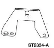 |
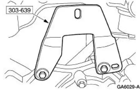
Special Tool(s) Support Bracket, Engine 303-639 |
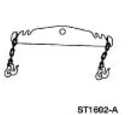 |
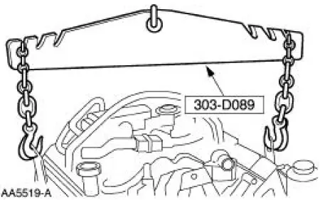
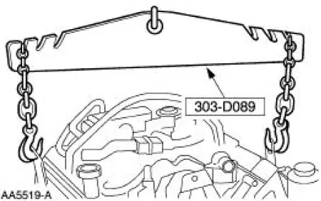
Spreader Bar 303-D089 (D93P-6001-A3) |
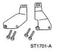 |
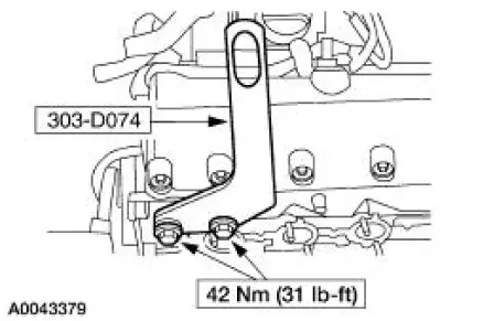
Lifting Bracket Set, Engine 303-D074 (D91P-6001-A) |
Removal
1. Remove the hood.
2. Remove the battery. For additional information, refer to Section.
3. Remove the air cleaner and outlet tube. For additional information, refer to Section.
4. Drain the engine cooling system.
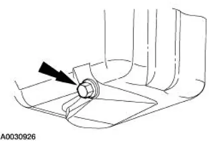
5. Remove the degas bottle.
6. Recover the A/C system. For additional information, refer to Section.
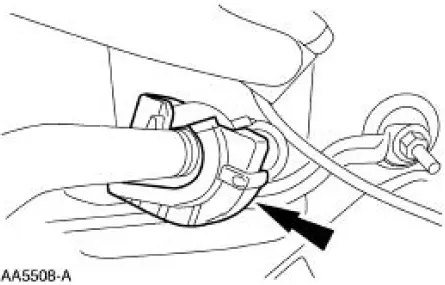
7. Disconnect the fuel lines. For additional information, refer to Section.
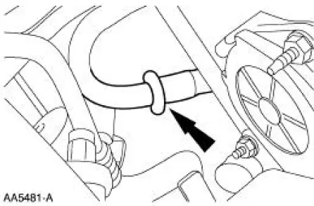
8. Disconnect the upper radiator hose from the water outlet connector.
9. Disconnect the throttle cable, speed control actuator cable and the return spring.
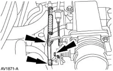
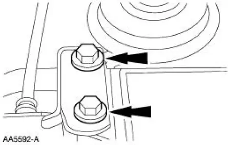
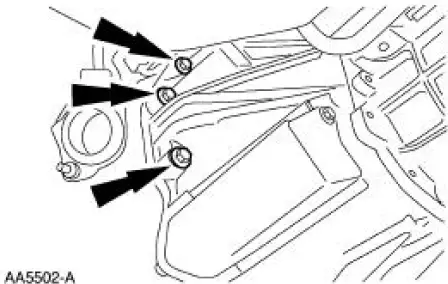
10. Remove the bolts and position the cables and bracket out of the way.
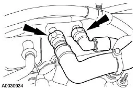
11. Disconnect the climate control vacuum supply hoses.
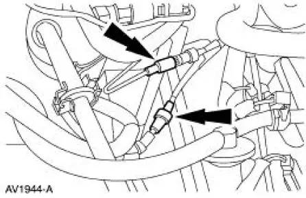
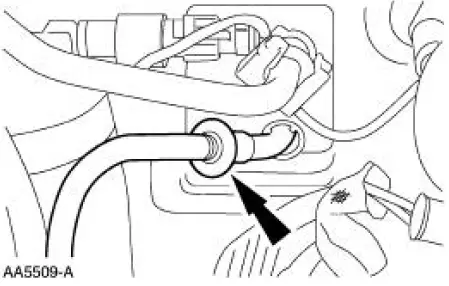
12. Disconnect the two heater water hoses.
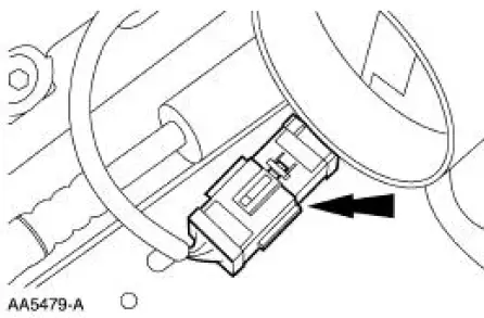
13. Disconnect the engine bulkhead connector.
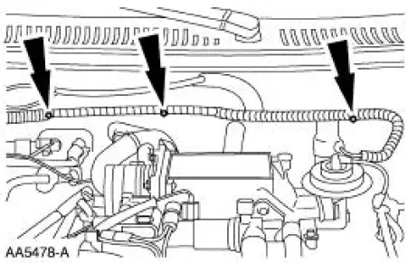
14. Separate the harness in three locations.
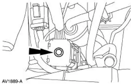
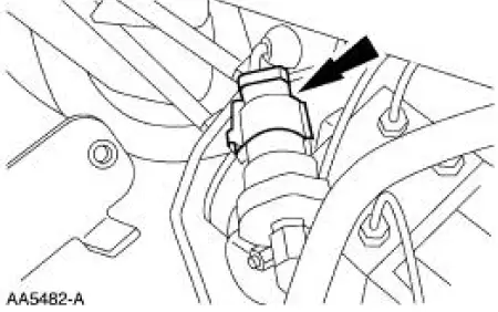
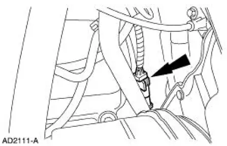
15. Disconnect the electrical connector.
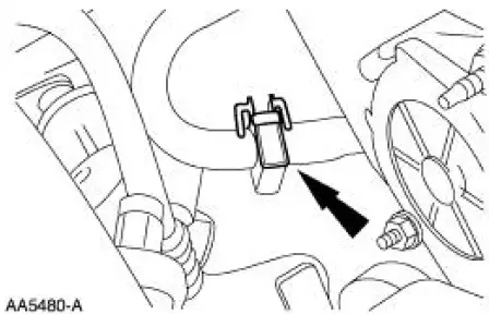
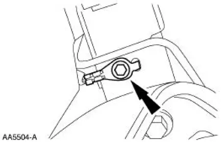
16. Remove the safety clip from the manifold suction tube.
17. Disconnect the A/C manifold suction tube.
18. Disconnect the A/C pressure cycle switch.
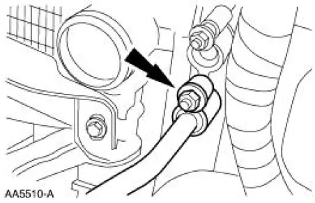
19. Remove the nut and separate the liquid tube from the A/C condenser.
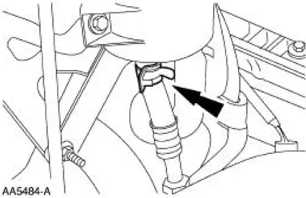
20. Disconnect the power steering hose from the reservoir.
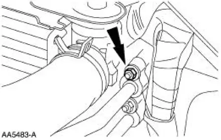
21. Remove the bolt and the body ground.
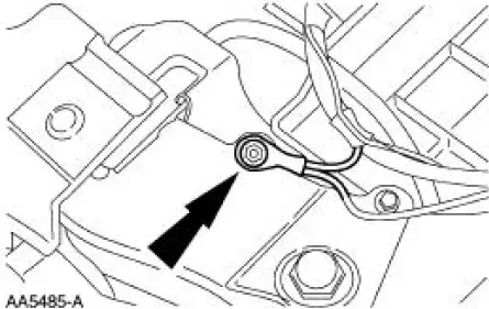
22. Separate the fuse link.
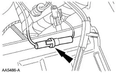
23. Disconnect the connector.
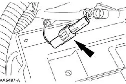
24. Disconnect the ground connector.
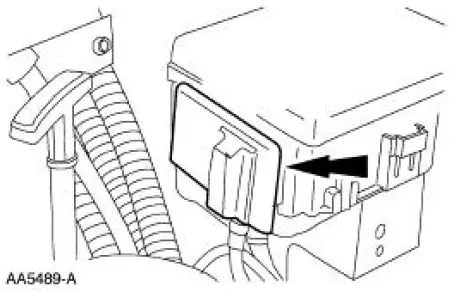
25. Slide the access cover up.
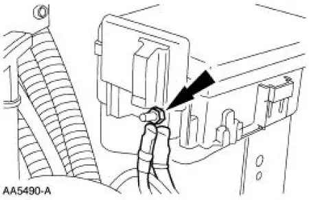
26. Remove the nut and the battery leads.
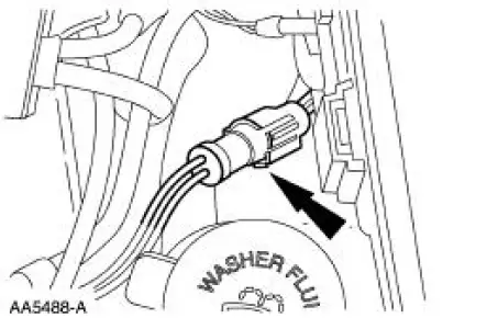
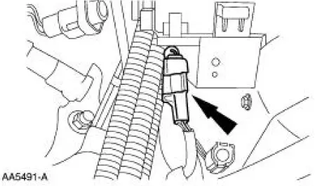
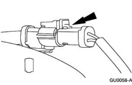
27. Disconnect the connector.
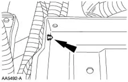
28. Separate the degas sensor lead from the battery tray.
29. Raise and support the vehicle. For additional information, refer to Section.
30. Drain the engine oil.
31. Disconnect the RH heated oxygen sensor connector.
32. Disconnect the LH heated oxygen sensor connector.
33. Remove the four exhaust manifold flange nuts.
34. Remove the starter. For additional information, refer to Section.
35. Remove the nine bell housing bolts.
36. Remove the bolt and the body ground.
37. Remove the power steering pump. For additional information, refer to Section.
38. Lower the vehicle.
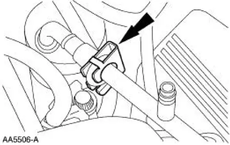
39. Remove the safety clip from the suction tube.
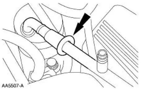
40. Disconnect the suction tube at the receiver/drier and remove the tube.
41. Remove the safety clip from the line at the evaporator core.
42. Disconnect the tube from the evaporator core.
43. Remove the nut and remove the tube from the vehicle.
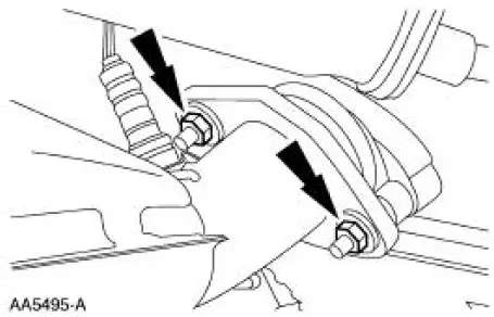
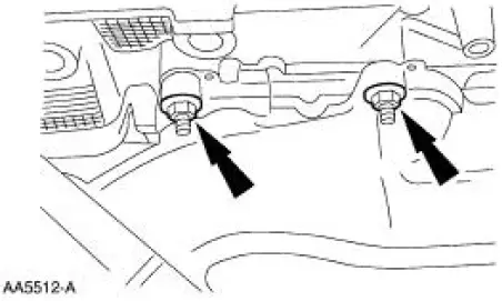
44. Remove the two nuts from the RH exhaust manifold.
45. Raise and support the vehicle. For additional information, refer to Section.
46. NOTE: The manifold will not be removed from the vehicle in this step.
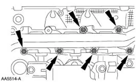
Remove the six exhaust manifold nuts.
47. Lower the vehicle.
48. Remove the generator. For additional information, refer to Section.
49. Install the special tool.
50. NOTE: This step will allow removal of the exhaust manifold through the bottom and access for the installation of the engine lift brackets.
Using a suitable floor crane, raise the engine to remove the exhaust manifold.
51. Install the RH and LH special tool.
52. NOTE: Before carrying out this step it will be necessary to support the transmission with a floor jack and a block of wood.
Install the special tool.
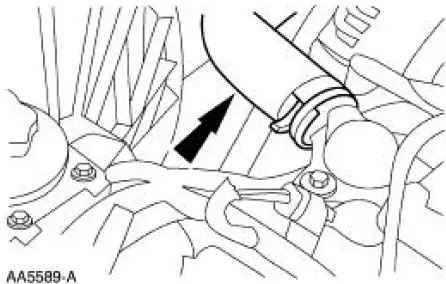
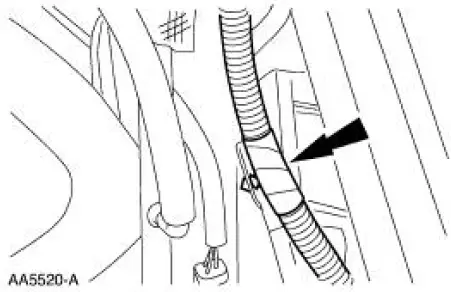
53. Separate the harness from the bracket.
- Raise the engine slightly to gain access to the transmission wiring support bracket.
54. NOTE: Adjust the transmission support jack as necessary to aid in the removal of the engine.
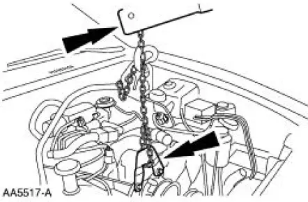
Using the special tool, remove the engine from the vehicle.
 Cylinder Heads (Removal)
Special Tool(s)
Remover, Crankshaft Vibration
Damper
303-009 (T58P-6316-D)
Remover, Crankshaft Front Oil
Seal
303-107 (T74P-6700-A)
Engine Lift Bracket Set
...
 Engine (Disassembly)
Special Tool(s)
Impact Slide Hammer
100-001 (T50T-100-A)
Remover, Crankshaft Rear Oil
Slinger
303-514 (T95P-6701-AH)
Remover, Crankshaft Rear Oil
Seal
303- ...
Other materials:
Pinpoint Tests - OSC Equipped Vehicles
Special Tool(s)
Breakout Box, EEC-V Control
System
418-049 (T94L-50-EEC-V) or
equivalent
MLP-TR Cable
418-F107 (007-00111) or
equivalent
Worldwide Diagnostic System
(WDS)
418-F224
New Generation STAR (NGS)
T ...
Storage Compartments
CENTER CONSOLE
Stow items in the cupholder carefully as items may become loose during
hard braking, acceleration or collisions, including hot drinks which may
spill.
Available console features include:
• Cupholders in the front of the
console (Pull the doo ...
Turn Signal and Hazard Lamps
Refer to Wiring Diagrams Cell 90 , Turn/Stop/Hazard Lamps for schematic
and connector information.
Special Tool(s)
73 III Automotive Meter
105-R0057 or equivalent
Inspection and Verification
1. Verify the customer concern.
2. Visually ins ...
