Ford Mustang (1999-2004) Service Manual: Reversing Lamps
Refer to Wiring Diagrams Cell 93 , Backup Lamps for schematic and connector information.
Special Tool(s)
 |
73III Automotive Meter or equivalent 105-R0057 |
Inspection and Verification
1. Verify the customer concern by operating the reversing lamps.
2. Visually inspect for obvious signs of mechanical and electrical damage; refer to the following chart:
Visual Inspection Chart
| Mechanical | Electrical |
|
|
3. If the concern is not visually evident, determine the symptom and proceed to Symptom Chart.
Symptom Chart
| Condition | Possible Sources | Action |
|
|
|
|
|
|
|
|
|
Pinpoint Tests
PINPOINT TEST R: THE REVERSING LAMPS ARE INOPERATIVE
| Test Step | Result / Action to Take |
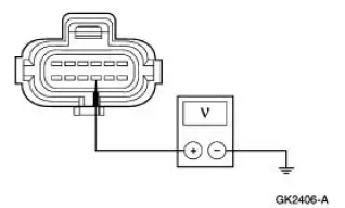
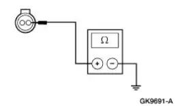
| R1 CHECK THE VOLTAGE TO THE DTR SENSOR (A/T) OR THE REVERSING LAMP SWITCH (M/T) | Yes GO to R2 . No REPAIR the circuit. TEST the system for normal operation. |
|
|
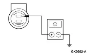
| R2 CHECK CIRCUIT 140 (BK/PK) FOR OPEN | Yes INSTALL a new DTR sensor (A/T) or reversing lamp switch (M/T); TEST the system for normal operation. No GO to R3 . |
|
|
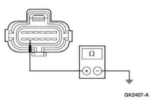
| R3 CHECK REVERSING LAMPS GROUND | Yes REPAIR Circuit 140 (BK/PK) for open. TEST the system for normal operation. No REPAIR the circuit. TEST the system for normal operation |
|
PINPOINT TEST S: THE INDIVIDUAL REVERSING LAMP IS INOPERATIVE
| Test Step | Result / Action to Take |
| S1 CHECK REVERSING LAMPS GROUND | Yes REPAIR Circuit 140 (BK/PK) for open. TEST the system for normal operation. No REPAIR the circuit. TEST the system for normal operation. |
|
PINPOINT TEST T: THE REVERSING LAMPS ARE ON CONTINUOUSLY
| Test Step | Result / Action to Take |
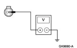
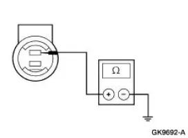
| T1 CHECK THE CONTINUITY OF THE DTR SENSOR (A/T) OR THE REVERSING LAMP SWITCH (M/T) | Yes REPAIR Circuit 140 (BK/PK) for short to battery. TEST the system for normal operation. No INSTALL a new DTR sensor (A/T) or reversing lamp switch (M/T); TEST the system for normal operation. |
|
 Fog Lamps
Refer to Wiring Diagrams Cell 86 , Fog Lamps for schematic and connector
information.
Special Tool(s)
73 III Automotive Meter or
equivalent
105-R0057
Principles of Operation
The f ...
 Headlamp Adjustment
Headlamp Aiming
1. The headlamp aiming procedure depends on the type of beam pattern the
headlamp is
equipped with. Vehicles may come equipped with visual optical right (VOR),
visual optical lef ...
Other materials:
Cleaning products
For best results, use the following products or products of equivalent
quality:
Motorcraft Bug and Tar Remover (ZC-42)
Motorcraft Custom Bright Metal Cleaner (ZC-15)
Motorcraft Detail Wash (ZC-3-A)
Motorcraft Dusting Cloth (ZC-24)
Motorcraft Engine Shampoo and ...
Hydro-Boost Bleeding
1. NOTE: The Hydro-Boost power brake booster (2B560) is generally
self-bleeding, and the
following procedure will normally bleed the air from the power brake booster.
Normal operation
of the vehicle will further remove any additional trapped air.
Fill the p ...
Bezel
Removal
1. Remove the shifter top control panel.
2. Disconnect the electrical connectors.
3. Remove the shifter bezel.
4. Remove the bulb from the bezel.
5. Disconnect the connector.
6. CAUTION: Extra force may be needed to lift up on the handle. Do not ...
