Ford Mustang (1999-2004) Service Manual: Headlamp Adjustment
Headlamp Aiming
1. The headlamp aiming procedure depends on the type of beam pattern the headlamp is equipped with. Vehicles may come equipped with visual optical right (VOR), visual optical left (VOL), or SAE only (includes sealed beam type) headlamps. To identify the headlamp beam pattern, look on the headlamp lens. Molded in small letters on the headlamp lens is one of the following:
- SAE
- VOR or SAE
- VOL or SAE
2. Once the headlamp beam pattern is identified, aim the headlamps using one of the following methods as applicable.
- Photometric aimers can aim SAE, VOR and VOL type headlamps. This is the preferred method of headlamp aiming.
- Visual or screen method aiming can be used to aim SAE, VOR and VOL type headlamps.
- Mechanical aimers can be used only with SAE type headlamps. Lamps that can be aimed mechanically will have three nibs molded into the lens of the lamp.
Photometric Aiming
1. For the photometric aiming procedure, refer to the appropriate photometric headlamp aimer instruction manual.
Screen Method Aiming
All headlamp types
NOTE: Horizontal aim is not necessary for VOR or VOL headlamps.
NOTE: Consult your state vehicle inspection manual for recommended tolerance ranges for visual aiming.
NOTE: The sight shield may need to be positioned or removed for access to the adjusters.
1. Before starting headlamp adjustment:
- Check the tire inflation.
- Check that no other load is in the vehicle other than a half tank of fuel.
- Check that the headlamps are clean.
- Check for correct headlamp operation.
- Check that the vehicle is on level ground.
- If the vehicle is equipped with air suspension, make sure that the switch is on.
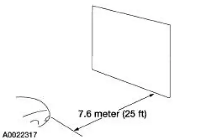
2. NOTE: The vertical wall or screen must be a minimum of 2.4 meters (8 feet) wide.
Park the vehicle on a level surface approximately 7.6 meters (25 feet) from the vertical wall or screen directly in front of it.
3. NOTE: The center of the lamp is marked by a 3 mm (0.12 in) circle on the headlamp lens.
Mark a horizontal reference line on the vertical wall or screen.
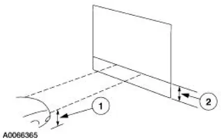
1. Measure the center of the headlamp height to ground and record.
2. Make a 2.4 meter (8 foot) horizontal mark (masking tape) on the vertical wall or screen at the same distance from the ground as previously recorded.
4. NOTE: This procedure should be done in a dark environment to effectively see the headlamp beam pattern.
Turn on the low beam headlamps to illuminate the wall or screen and open the hood.
5. NOTE: For SAE type headlamps, the appearance of the beam pattern may vary between vehicles.
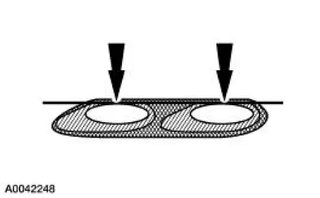
On the wall or screen, locate the high intensity area of the beam pattern. Place the top edge of the high intensity zone even with the horizontal reference line.
VOR type headlamps
6. NOTE: The appearance of the VOR beam pattern may vary between vehicles.
Identify at the top edge of this high intensity area a distinct horizontal cutoff in the beam pattern.
If the top edge of this cutoff is not even with the horizontal reference line, the headlamp beam will need to be adjusted.
VOL type headlamps
7. For VOL type headlamps, there will be a distinct cutoff in the left portion of the beam pattern.
The edge of this cutoff should be positioned 50.2 mm (2 in) below the horizontal reference line.
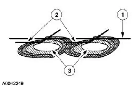
1. Horizontal reference line.
2. Top edge of the beam pattern.
3. High intensity zone.
Mechanical Aiming
1. For the mechanical aiming procedure, refer to the appropriate mechanical headlamp aimer instruction manual.
 Reversing Lamps
Refer to Wiring Diagrams Cell 93 , Backup Lamps for schematic and
connector information.
Special Tool(s)
73III Automotive Meter or
equivalent
105-R0057
Inspection and Verification
...
 Bulb - Headlamp
Removal
WARNING: The halogen bulb contains gas under pressure. The bulb may
shatter if the
glass envelope is scratched or if the bulb is dropped. Handle the bulb only
by its base. Grasp
the bul ...
Other materials:
Axle Assembly
Removal and Installation
1. CAUTION: The vehicle must be on level ground and at curb height.
Mark the rear shock absorbers relative to their protective sleeve.
During installation, raise the suspension to this reference mark before
tightening the
suspens ...
Ignition Switch
Removal
1. Disconnect the battery ground cable.
2. Remove the lower instrument panel steering column cover.
1. Remove the screws.
2. Remove the lower instrument panel steering column cover.
3. Remove the instrument panel reinforcement.
1. Rem ...
Handle - Interior Door
Removal
1. Remove the door trim panel (23942). For additional information,
refer to Section.
2. Remove the rivet.
3. Remove the cable clip.
4. Release the cable housing from the interior handle.
5. Release the actuating cable from the interior ha ...
