
Ford Mustang (1999-2004) Service Manual: Roller Followers
Special Tool(s)
|
|
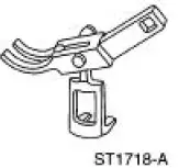
Compressor, Valve Spring 303-452 (T93P-6565-AR) |
Removal and Installation
1. Remove the LH and RH valve cover. For additional information, refer to Valve Cover LH and Valve Cover RH in this section.
2. Position the piston of the cylinder being repaired at the bottom of the stroke and camshaft lobe at base circle.
3. Using the special tool, compress the intake valve spring and remove the roller follower.
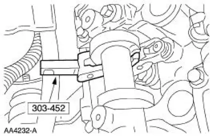
4. Using the special tool, compress the exhaust valve spring and remove the roller follower.
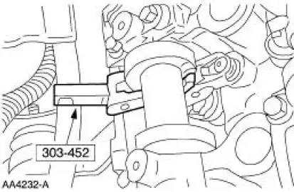
5. Repeat Steps 2, 3 and 4 to remove all the necessary roller followers. Inspect roller finger followers and camshafts. For additional information, refer to Section.
6. To install, reverse the removal procedure.
 Hydraulic Lash Adjusters
Removal
1. Remove the roller followers. For additional information, refer to Roller
Followers in this section.
2. Remove the 16 hydraulic lash adjusters.
3. Inspect the roller followers. For addit ...
 Camshaft
Special Tool(s)
Holding Tool, Camshaft
303-446 (T93P-6256-AHR)
Material
Item
Specification
Super Premium SAE 5W-20
Engine Oil
XO-5W20-QSP or equivalent
WSS-M2C153-
...
Other materials:
Brake Caliper Support Bracket
Removal
1. Raise and support the vehicle.
2. Remove the tire and wheel assembly.
3. CAUTION: Do not allow the rear disc brake caliper (2552) to
hang from the rear
wheel brake hose (2A442)
Remove the rear disc brake caliper bolts and position the ...
Supplementary Restraints System
PRINCIPLES OF OPERATION
WARNING: Airbags do not inflate slowly or gently, and the risk
of injury from a deploying airbag is the greatest close to the trim
covering the airbag module.
WARNING: All occupants of your vehicle, including the driver,
should always p ...
System Flushing - CII Power Steering Pump
WARNING: Do not mix oil types. Any mixture or any unapproved oil can
lead to seal
deterioration and leaks. A leak can ultimately cause loss of fluid, which can
result in a loss of
power steering assist.
1. Remove the fuel pump fuse from the battery junction ...
