Ford Mustang (1999-2004) Service Manual: Link - Stabilizer Bar
Removal
CAUTION: Suspension fasteners are critical parts because they affect performance of vital components and systems and their failure can result in major service expense. A new part with the same part number or an equivalent part must be installed, if installation is necessary. Do not use a part of lesser quality or substitute design. Torque values must be used as specified during reassembly to ensure correct retention of these parts.
1. Raise the vehicle on a hoist.
2. Disconnect the front stabilizer bar links (5K483) from the front stabilizer bar (5482).
1. Remove the nuts and bushings. Discard the nuts.
2. Rotate the stabilizer bar to disconnect the links.
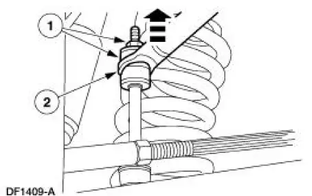
3. Remove the stabilizer bar links.
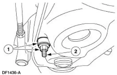
1. Remove the nuts and bushings.
2. Remove the stabilizer bar links.
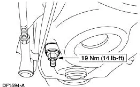
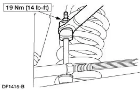
Installation
1. To install, reverse the removal procedure.
 Bar - Stabilizer
Removal
CAUTION: Suspension fasteners are critical parts because they affect
performance of vital
components and systems and their failure can result in major service expense. A
new part with
the sa ...
 Bushing - Stabilizer Bar
Removal
CAUTION: Suspension fasteners are critical parts because they affect
performance of vital
components and systems and their failure can result in major service expense. A
new part with
the sa ...
Other materials:
Engine Ignition (Description and Operation)
The ignition coil (12029), which is mounted on the upper intake manifold, can
be described as a coil
pack containing three separate coil units. Each coil unit is individually
controlled by the powertrain
control module (PCM) (12A650) through separate wire le ...
HomeLink® wireless control system
WARNING: Make sure that the garage door and security device
are free from obstruction when you are programming. Do not
program the system with the vehicle in the garage.
WARNING: Do not use the system with any garage door opener
that does not have the safety s ...
Gearshift Lever and Boot
Material
Removal and Installation
1. Remove the gearshift lever knob.
2. Remove the console panel gearshift plate. Lift the gearshift lever boot
over the gearshift lever.
3. Remove the bolts and the shift lever.
4. Remove the screws and the inner shif ...
