Ford Mustang (1999-2004) Service Manual: Switch - Seat Regulator Control
Removal and Installation
1. Disconnect the battery. For additional information, refer to Section.
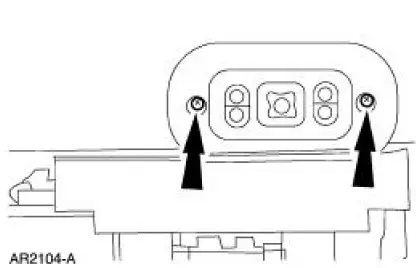
2. Remove the screws and position the seat regulator control switch aside.
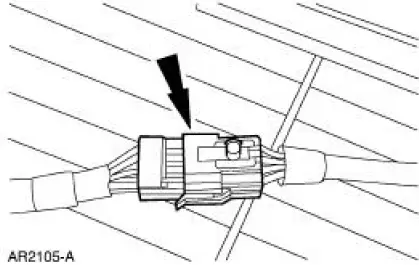
3. Disconnect the electrical connector and remove the seat regulator control switch.
4. To install, reverse the removal procedure.
 Seats (Diagnosis and Testing)
Refer to Wiring Diagrams Cell 120 , Power Seats for schematic and
connector information.
Refer to Wiring Diagrams Cell 122 , Power Lumbar Seats for schematic and
connector information.
Special ...
 Lumbar Control Switch
Removal and Installation
All vehicles
1. Remove the front seat. For additional information, refer to Seat-Front
Power in this section.
Vehicles with standard power lumbar
2. Pull to remove the l ...
Other materials:
Installation
1. CAUTION: Do not allow grease, oil, brake fluid or other
contaminants to contact the
pad lining material. Do not install contaminated pads.
NOTE: Install all hardware supplied with pad kits.
Install the pads.
1. Install the new pad slippers. ...
Installation
Lift cylinder
1. NOTE: Be sure that each fitting is installed in the correct position on
the folding top hydraulic
component.
NOTE: Make sure that the tetra seal is installed in the bottom of each of the
folding top
hydraulic cylinder ports before attaching ...
Mass Air Flow (MAF) Sensor - Mach I
Removal
CAUTION: The mass air flow (MAF) sensor hot wire sensing
element and housing are
calibrated as a unit and must be repaired as a complete assembly. Do not
damage the sensing
element (internal to housing) or possible failure to the mass air f ...
