Ford Mustang (1999-2004) Service Manual: Lumbar Control Switch
Removal and Installation
All vehicles
1. Remove the front seat. For additional information, refer to Seat-Front Power in this section.
Vehicles with standard power lumbar
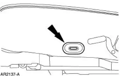
2. Pull to remove the lumbar control switch (14C715).
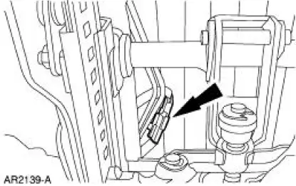
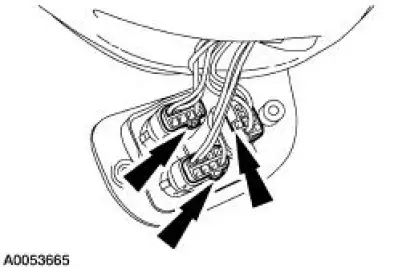
3. Disconnect the power lumbar support air hoses.
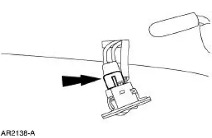
4. Disconnect the lumbar seat control switch electrical connector.
5. Remove the lumbar seat control switch.
Vehicles with power bolster and lumbar
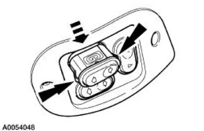
6. Remove the two screws for the power bolster and lumbar switch bezel.
7. Disconnect the power lumbar switch and the bolster switches.
8. Pinch the release tabs on the affected switch and push the switch through the bezel.
All vehicles
9. To install, reverse the removal procedure.
 Switch - Seat Regulator Control
Removal and Installation
1. Disconnect the battery. For additional information, refer to Section.
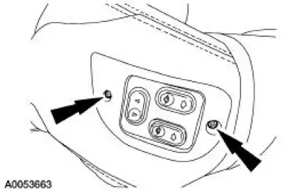
2. Remove the screws and position the seat regulator control switch aside.
3. Disconnect the elec ...
 Front Seat Backrest
Removal and Installation
All vehicles
1. Remove the seat. For additional information, refer to Seat-Front Power
in this section.
2. Remove the front seat backrest latch. For additional informati ...
Other materials:
Entertainment System - General Information
Audio System (Diagnosis and Testing)
Refer to Wiring Diagrams Cell 130 , Radio for schematic and connector
information.
Special Tool(s)
73III Automotive Meter
105-R0057 or equivalent
Inspection and Verification
1. Verify the customer con ...
Air Bag Supplemental Restraint System (SRS) (Description and Operation)
The air bag supplemental restraint system (SRS) is designed to provide
increased collision protection
for front seat occupants in addition to that provided by the three-point safety
belt system. Safety belt
use is necessary to obtain the best occupant protec ...
Air Cleaner - 4.6L (2V) and 4.6L (4V)
Removal and Installation
Mach I
1. Disconnect the air intake scoop outlet tube.
All vehicles
2. Remove the air cleaner outlet tube from the throttle body. For
additional information, refer to Air
Cleaner Outlet Pipe-4.6L (2V) or Air Cleaner Outlet Pipe- ...
