Ford Mustang (1999-2004) Service Manual: Synchronizers
Disassembly
NOTE: This procedure applies to all synchronizer assemblies (7124). The synchronizers are slightly different in design. Notation is made where procedural differences occur.
1. On the third/fourth speed synchronizer and the fifth speed synchronizer, scribe an alignment mark on the sliding sleeve and the hub for assembly reference.
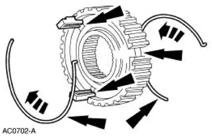
2. NOTE: Only the synchronizer hub insert springs (7109) and the synchronizer hub inserts (7A044) are available separately.
Remove the synchronizer hub inserts and the hub insert springs.
3. The first/second speed synchronizer sliding sleeve, the hub, and the output shaft are an assembly. Do not attempt to separate the hub from the output shaft. Discard the entire assembly if wear or damage to the synchronizer or output shaft is evident.
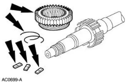
4. On the third/fourth speed synchronizer and the fifth speed synchronizer, remove the sliding sleeve.
Assembly
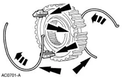
1. NOTE: Both synchronizer hub insert springs engage the same synchronizer hub insert but rotate in the opposite direction.
NOTE: The third/fourth speed synchronizer uses the winged synchronizer hub inserts.
Install the synchronizer hub inserts and the hub insert springs. Verify that the spring tabs are positioned over the hub inserts.

2. CAUTION: Match the alignment marks made during disassembly. The sleeve and the hub have an extremely close fit. Hold the sleeve and hub square to prevent jamming.
Do not force the sleeve onto the hub.
On the third/fourth speed synchronizer and the fifth speed synchronizer, install the sliding sleeve.
 Countershaft Bearing
Special Tool(s)
Bearing Replacer
308-061 (T77J-7025-L)
Front Bearing Replacer
308-062 (T77J-7025-M)
Mainshaft Front Bearing
Replacer
308-081 (T82T-7003-DH)
...
 Transmission (Assembly)
Special Tool(s)
Dial Indicator with Bracketry
100-002 (TOOL-4201-C) or
Equivalent
Gauge, Clutch Housing
308-021 (T75L-4201-A)
Extension Housing Seal
Replacer ...
Other materials:
Knock
Knock, which can occur on all driving phases, has several causes including
damaged teeth or gearset.
In most cases, one of the following conditions will occur:
1. A gear tooth damaged on the drive side is a common cause of the knock.
This can usually be
cor ...
Driveshaft (Removal and Installation)
Material
Item
Specification
Threadlock and
Sealer
E0AZ-19554-AA
WSK-M2G351-A5 (type
II)
Removal and Installation
1. Raise and support the vehicle.
2. Carry out the following:
1. Place an index mark on the rear axle pinion flange and ...
Pinpoint Test F: LFC 16/DTC B1888 - Passenger Air Bag Circuit Shorted to
Ground
Normal Operation
The restraints control module (RCM) checks for passenger air bag circuit
shorts to ground by
monitoring the voltage of circuits 607 (LB/OG) and 616 (PK/BK) at pins 6 and
7. If the RCM detects a
short to ground on either of these pins, i ...
