Ford Mustang (1999-2004) Service Manual: System Air Flow Description
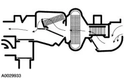
MAX A/C
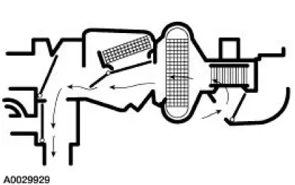
When MAX A/C is selected:
- The air inlet door vacuum control motor is at full vacuum, closing off outside air and admitting only recirculated air.
- The panel/defrost door vacuum control motor is at full vacuum and the panel/floor door vacuum control motor is at no vacuum, directing airflow to the instrument panel A/C registers. A small amount of airflow from the side window demisters will be present.
- Blended air temperature is available.
- The A/C compressor will operate if the outside temperature is above approximately 6C (43F).
- The blower motor is on.
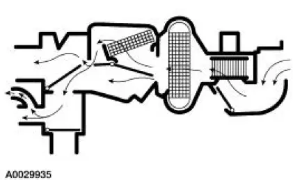
NORM A/C
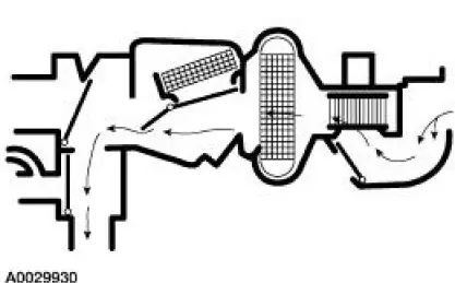
When NORM A/C is selected:
- The air inlet door vacuum control motor is at no vacuum, admitting only outside air into the passenger compartment.
- The panel/defrost door vacuum control motor is at full vacuum and the panel/floor door vacuum control motor is at no vacuum, directing airflow to the instrument panel A/C registers. A small amount of airflow from the side window demisters will be present.
- Blended air temperature is available.
- The A/C compressor will operate if the outside air temperature is above approximately 6C (43 F).
- The blower motor is on.
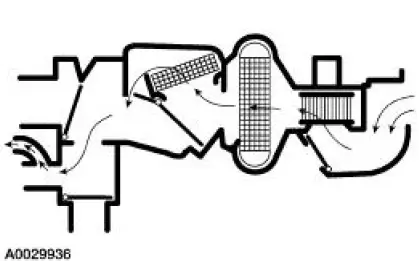
PANEL
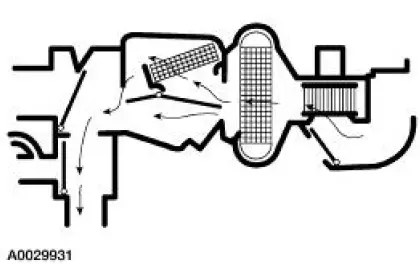
When PANEL is selected:
- The air inlet door vacuum control motor is at no vacuum, admitting only outside air into the passenger compartment.
- The panel/defrost door vacuum control motor is at full vacuum and the panel/floor door vacuum control motor is at no vacuum, directing airflow to the instrument panel A/C registers. A small amount of airflow from the side window demisters will be present.
- The temperature can be adjusted to heat the air, but the air cannot be cooled below the outside temperature.
- The A/C compressor will not operate.
- The blower motor is on.
OFF
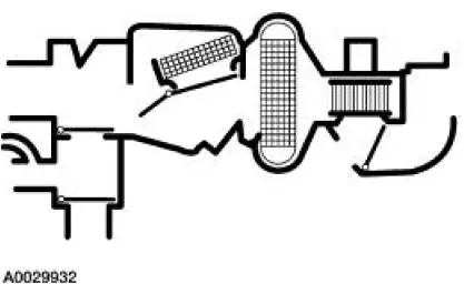
When OFF is selected:
- The air inlet door vacuum control motor is at full vacuum, closing off outside air from entering the passenger compartment.
- The panel/floor door vacuum control motor is at full vacuum and the panel/defrost door vacuum control motor is at no vacuum, closing off airflow to the defrost duct, side window demisters, floor duct and instrument panel A/C registers.
- The A/C compressor will not operate.
- The blower motor is off.
FLOOR
When FLOOR is selected:
- The air inlet door vacuum control motor is at no vacuum, admitting only outside air into the passenger compartment.
- The panel/floor door vacuum control motor is at full vacuum and the panel/defrost door vacuum control motor is at no vacuum, directing airflow to the floor duct. A small amount of airflow from the side window demisters will be present.
- The temperature can be adjusted to heat the air, but the air cannot be cooled below the outside temperature.
- The A/C compressor will not operate.
- The blower motor is on.
FLOOR/DEFROST
When FLOOR/DEFROST is selected:
- The air inlet door vacuum control motor is at no vacuum, admitting only outside air into the passenger compartment.
- The panel/floor door vacuum control motor is at partial vacuum and the panel/defrost door vacuum control motor is at no vacuum, directing airflow to the floor duct, the defroster duct, and the side window demisters.
- The temperature can be adjusted to heat or cool the air below the outside temperature.
- The A/C compressor will operate if the outside air temperature is above approximately 6C (43 F).
- The blower motor is on.
DEFROST
When DEFROST is selected:
- The air inlet door vacuum control motor is at no vacuum, admitting only outside air into the passenger compartment.
- The panel/floor door and panel/defrost door vacuum control motors are at no vacuum, directing airflow to the defroster duct and the side window demisters.
- The temperature can be adjusted to heat or cool the air below the outside temperature.
- The A/C compressor will operate if the outside air temperature is above approximately 6C (43 F).
- The blower motor is on.
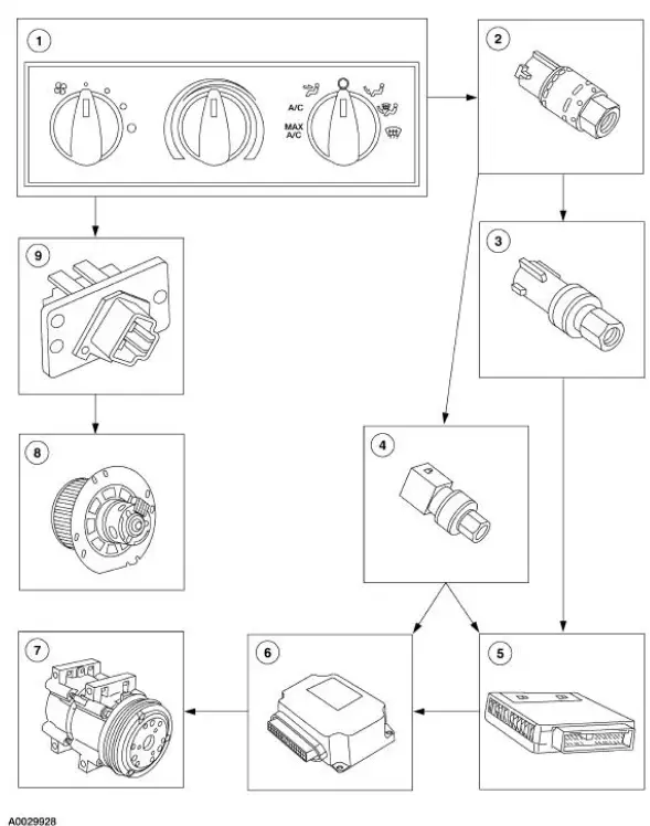
Electrical Components

 Principles of Operation
There are four main principles involved with the basic theory of
operation:
heat transfer
latent heat of vaporization
relative humidity
effects of pressure
Heat Transfer
If two substan ...
 Climate Control System (Diagnosis and Testing)
Refer to Wiring Diagrams Cell 54 , Air Conditioner/Heater for schematic
and connector information.
Special Tool(s)
Connector, Refrigerant
Pressure Line
412-093 (T94P-19623-E)
...
Other materials:
Register - LH
Removal
1. Remove the instrument panel steering column cover bolts.
2. Unsnap and remove the instrument panel steering column cover.
3. Remove the bolts and the steering column reinforcement.
4. Remove the screws.
5. Remove the register.
Installation ...
Installation
1. Make sure the anti-rattle spring is correctly positioned in the
caliper.
2. CAUTION: Make sure guide pin boots are correctly seated or damage to
guide pins
can occur.
Install the disc brake caliper.
1. Hold the guide pins stationary.
2. Inst ...
Entertainment System - General Information
Audio System (Diagnosis and Testing)
Refer to Wiring Diagrams Cell 130 , Radio for schematic and connector
information.
Special Tool(s)
73III Automotive Meter
105-R0057 or equivalent
Inspection and Verification
1. Verify the customer con ...
