Ford Mustang (1999-2004) Service Manual: Climate Control System (Diagnosis and Testing)
Refer to Wiring Diagrams Cell 54 , Air Conditioner/Heater for schematic and connector information.
Special Tool(s)
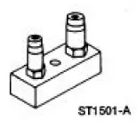 |
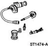
Connector, Refrigerant Pressure Line 412-093 (T94P-19623-E) |
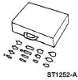 |
Set, A/C Fittings 412-DS028 (014-00333, D93L- 19703-B) or equivalent |
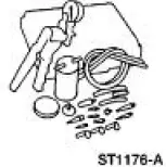 |
Vacuum Pump Kit 416-D002 (D95L-7559-A) or equivalent |
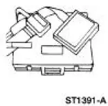 |
Breakout Box, EEC-V Control System 418-049 (014-00950, T94L-50- EEC-V) |
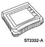 |
Worldwide Diagnostic System (WDS) 418-F224, New Generation STAR (NGS) Tester 418-F052, or equivalent diagnostic tool |
 |
Pressure Test Kit 014-R1072 or equivalent |
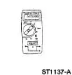 |
77 III Automotive Meter 105-R0056 or equivalent |
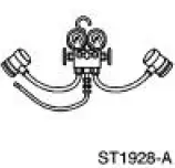 |
R-134a Manifold Gauge Set 176-R032A or equivalent |
 |
Refrigerant Leak Detector 216-00001 or equivalent |
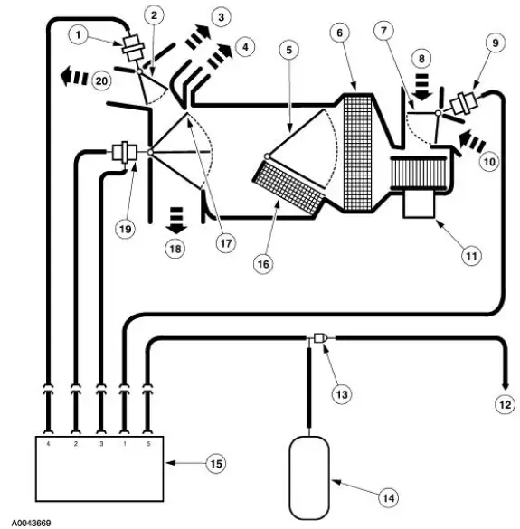
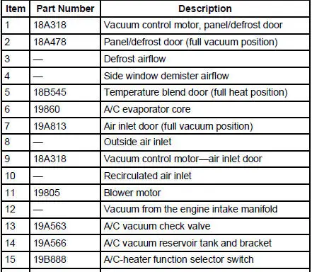
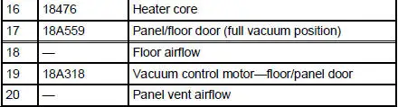
Vacuum Schematic-Manual Climate Control System
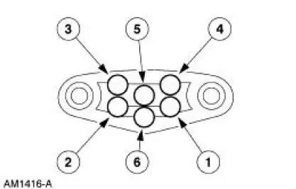
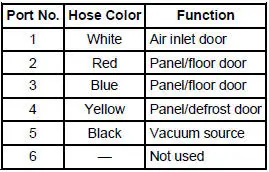
Function Selector Switch Vacuum Connector
Function Selector Switch Vacuum Application Chart
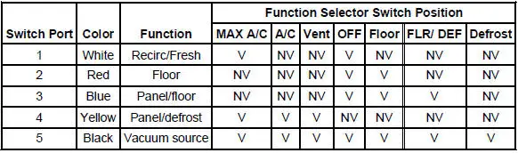
V=Vacuum
NV=No Vacuum
 System Air Flow Description
MAX A/C
When MAX A/C is selected:
The air inlet door vacuum control motor is at full vacuum, closing
off outside air and admitting
only recirculated air.
The panel/defrost door vacuum cont ...
 Inspection and Verification
1. Verify the customer's concern by operating the climate control system
to duplicate the condition.
2. Inspect to determine if one of the following mechanical or electrical
concerns apply:
Visu ...
Other materials:
Valve Seals
Special Tool(s)
Valve Spring Compressor
303-452 (T93P-6565-AR)
Valve Stem Seal Replacer
303-383 (T91P-6571-A)
Compressor, Valve Spring
(Exhaust)
303-567 (T97P- 6565-AH)
Material
Item
Specification
Supe ...
Switch - Seat Regulator Control
Removal and Installation
1. Disconnect the battery. For additional information, refer to Section.
2. Remove the screws and position the seat regulator control switch aside.
3. Disconnect the electrical connector and remove the seat regulator control
swit ...
Economical driving
Fuel economy is affected by several things, such as how you drive, the
conditions you drive under and how you maintain your vehicle.
There are some things to keep in mind that may improve your fuel
economy:
• Accelerate and slow down in a smooth, moderate f ...
