Ford Mustang (1999-2004) Service Manual: Driveline Angle
| Item | Description |
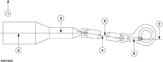
| 1 | Bottom of the frame |
| 2 | Engine crankshaft centerline |
| 3 | Engine angle |
| 4 | Driveshaft and coupling shaft centerline |
| 5 | Driveshaft and coupling shaft angle |
| 6 | Rear axle pinion centerline |
| 7 | Axle pinion angle |
An incorrect driveline (pinion) angle can often be detected by the driving condition in which the vibration occurs.
- A vibration during coastdown from 72 to 56 km/h (45 to 35 mph) is often caused by an excessive U-joint angle at the axle (pinion nose downward).
- A vibration during acceleration, from 56 to 72 km/h (35 to 45 mph) may indicate an excessive Ujoint angle at the axle (pinion nose upward).
When these conditions exist, check the driveline angles as described in the General Procedures portion of this section.
If the tires and driveline angle are not the cause, carry out the NVH tests to determine whether the concern is caused by a condition in the axle.
Universal Joint (U-Joint) Wear
Place the vehicle on a frame hoist and rotate the driveshaft by hand. Check for rough operation or seized U-joints. Install a new U-joint if it shows signs of seizure, excessive wear, or incorrect seating.
 Analysis of Vibration
WARNING: A vehicle equipped with a Traction-Lok differential will
always have both
wheels driving. If only one wheel is raised off the floor and the rear axle is
driven by the engine,
the wheel on t ...
 Wheel Hub or Axle Flange Bolt Circle Runout
NOTE: The brake discs must be removed to carry out all runout
measurements.
1. Position the special tool perpendicular to the wheel hub or axle flange bolt,
as close to the hub
or flange face as po ...
Other materials:
Input Shaft and Bearing
Special Tool(s)
Input Shaft Seal Replacer
308-220 (T94P-7025-AH)
Pinion Bearing Cone Remover
205-D002 (D79L-4621-A) or
Equivalent
Disassembly
1. Using the special tool and a press, remove the input bearing (7025).
2. Remove t ...
Wheel Hub and Bearing
Removal
CAUTION: Suspension fasteners are critical parts because they affect
performance of vital
components and systems and their failure can result in major service expense. A
new part with
the same part number or an equivalent part must be installed, if i ...
Installation
Using special tool 205-024
NOTE: This is the preferred method for installing the pinion bearing
cups. If necessary, proceed to
Using special tools 205-153, 205-024, 205-231, and 205-D055 in this procedure
for an alternate
method.
1. Position the special too ...
