Ford Mustang (1999-2004) Service Manual: Disassembly
1. Remove the driveshaft (4602). For additional information, refer to Driveshaft in this section.
2. CAUTION: Under no circumstances is the driveshaft assembly to be clamped in the jaws of a vise or similar holding fixture. Denting or localizing fracture can result, causing driveshaft failure during vehicle operation.
Place the driveshaft on a suitable workbench, being careful not to damage the tube.
3. NOTE: If components are not marked and installed correctly, driveline imbalance can occur.
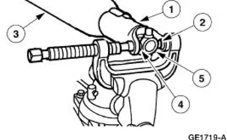
Index-mark the positions of the driveshaft components.
4. Clamp the U-joint tool in a vise.
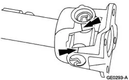
5. Remove all four of the snap rings.
6. Remove the driveshaft flange yoke.
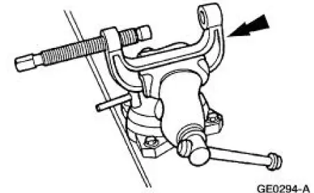
1. Position the driveshaft flange yoke in the U-joint tool.
2. Press out a bearing cup.
3. Remove the driveshaft flange yoke.
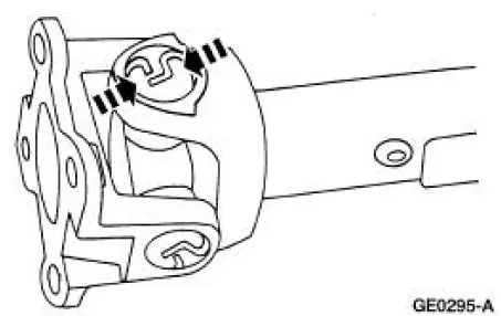
4. Press on the spider to remove the remaining bearing cup.
5. Remove the driveshaft flange yoke.
7. Remove the spider.
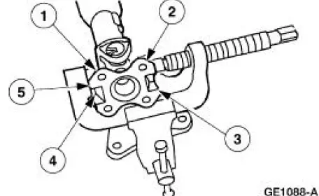
1. Reposition the driveshaft in the U-joint tool.
2. Press out the bearing cup.
3. Rotate the driveshaft.
4. Press on the spider to remove the remaining bearing cup.
5. Remove the spider.
8. Clean the yoke area at the end of the driveshaft.
 Universal Joint - Single Cardan, Flange Yoke
Special Tool(s)
Installer/Remover, C Frame
and Screw
205-086 (T74P-4635-C)
...
 Assembly
1. NOTE: Universal joint kits are to be installed as complete
assemblies only. Do not mix
components from other U-joint kits.
Install the spider.
1. Start a new bearing cup into the driveshaft yok ...
Other materials:
Crankshaft Pulley
Special Tool(s)
Remover, Crankshaft Vibration
Damper
303-009 (T58P-6316-D)
Installer, Crankshaft Vibration
Damper
303-102 (T74P-6316-B)
Material
Item
Specification
Silicone Gasket and Sealant
F7AZ-19554-EA or eq ...
Manual seats
WARNING: Do not adjust the driver’s seat or seatback while the
vehicle is moving.
WARNING: Rock the seat backwards and forwards after
releasing the lever to make sure that it is fully engaged.
Moving the seats backward and
forward
Recline adjustment
WARNIN ...
Disassembly
1. CAUTION: Do not place the cylinder head flat on the bench; the
valves will bend.
CAUTION: Before disassembly begins, mark the valve position on the face of each
valve being removed. The valves must be re-installed into the same positions.
Install the spec ...
