
Ford Mustang (1999-2004) Service Manual: Universal Joints
The universal joints are:
- lubed-for-life design and require no lubrication.
- equipped with nylon thrust washers, located at each base of the bearing cup, which control end play, position the needle bearing and improve grease movement.
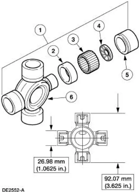
| Item | Part Number | Description |
| 1 | 4635 | Universal joint (U-joint) |
| 2 | - | Grease seal (part of 4635) |
| 3 | - | 32 needle bearings (part of 4635) |
| 4 | - | Thrust washer (part of 4635) |
| 5 | - | Bearing cup (part of 4635) |
| 6 | - | Spider (part of 4635) |
 Driveshaft (Description and Operation)
NOTE: All driveshaft assemblies are balanced. If undercoating the
vehicle, protect the driveshaft to
prevent overspray of any undercoating material.
The driveshaft has the following features ...
 Driveshaft (Removal and Installation)
Material
Item
Specification
Threadlock and
Sealer
E0AZ-19554-AA
WSK-M2G351-A5 (type
II)
Removal and Installation
1. Raise and support the vehicle.
2. Carry out the following:
...
Other materials:
Exhaust System (Diagnosis and Testing)
Symptom Chart
Condition
Possible Sources
Action
Noisy or
leaking
exhaust
Broken or loose
clamps, hangers or
isolators.
Punctures in the muffler
(5230).
Broken, loose or
missing exhaust
manifold fa ...
Installation
1. NOTE: A new torque converter drain plug must be used.
Install the torque converter drain plug.
2. Install the torque converter housing plug.
3. CAUTION: If installing a new filter, and the seal remains in the
main control bore,
carefully use a small ...
Automatic climate control
Note: To use the touchscreen controls, see the Touchscreen climate
controls in the Navigation System chapter.
A. CLIMATE: Control the system through the touchscreen display.
See Touchscreen functions later in this section.
B. Rear defrost: Turns the heated ...
