
Ford Mustang (1999-2004) Service Manual: Valve Cover RH
Material
| Item | Specification |
| Silicone Gasket and Sealant F7AZ-19554-EA or equivalent | WSE-M4G323-A4 |
Removal and Installation
1. Remove the air cleaner outlet tube. For additional information, refer to Section.
2. Disconnect the fuel line. For additional information, refer to Section.
3. Separate the engine wiring harness from the valve cover studs.
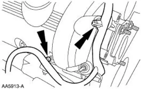
4. Separate the engine wiring harness from the valve cover studs.
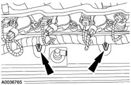
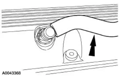
5. Remove the positive crankcase ventilation (PCV) hose from the valve cover and position aside.
6. Raise and support the vehicle. For additional information, refer to Section.
7. Remove the bolt and position the transmission filler tube aside.
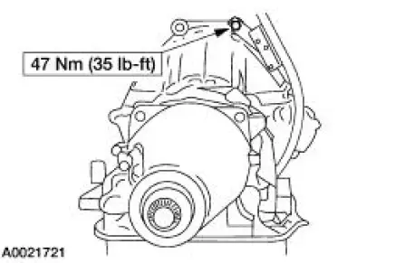
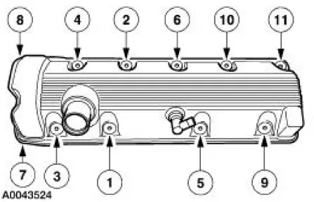
8. Remove the bolts, studs and the valve cover in the sequence shown.
- Clean and inspect the sealing surfaces.
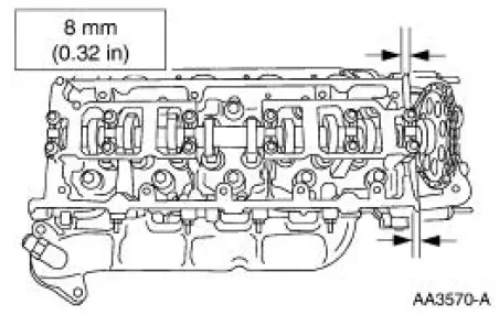
9. NOTE: Apply an eight millimeter bead of silicone gasket and sealant at the intersection of the engine front cover and the cylinder head.
To install, reverse the removal procedure.
 Installation
1. Install the intake manifold and gaskets, tighten the bolts in the sequence
shown.
2. NOTE: The O-ring is to be installed on the top of the thermostat.
Install the water thermostat and the O-rin ...
 Valve Cover LH
Material
Item
Specification
Silicone Gasket and Sealant
F7AZ-19554-EA or equivalent
WSE-M4G323-A4
Removal and Installation
1. Position the oil level tube (6754) out of the way.
2 ...
Other materials:
Manual Transaxle/Transmission - T56
General Specifications
Torque Specifications
...
Accelerator Pedal and Shaft
Removal and Installation
1. Push the accelerator cable nylon bushing out of the accelerator pedal and
shaft arm.
2. Remove the accelerator pedal and shaft.
Remove the nuts.
Remove the accelerator pedal and shaft.
3. To install, reverse the removal pro ...
Installation
1. NOTE: If the valve cover is not secured within four minutes, the sealant
must be removed and
the sealing area cleaned with metal surface cleaner. Allow to dry until there is
no sign of
wetness, or four minutes, whichever is longer. Failure to follow this ...
