Ford Mustang (1999-2004) Service Manual: Release Cable - Clutch
Removal
CAUTION: Whenever the clutch release lever cable (7K553) is disconnected for any reason, such as transmission removal, clutch pedal components or clutch release lever cable replacement, it is imperative the correct method for installing the clutch release lever cable be followed. Incorrect installation may damage components or cause system failure.
1. Remove the instrument panel steering column cover.
1. Remove the screws.
2. Remove the instrument panel steering column cover.
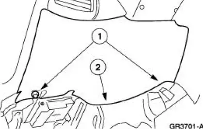
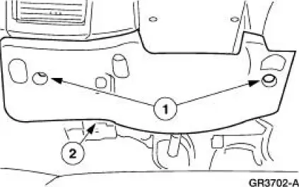
2. Remove the instrument panel reinforcement.
1. Remove the screws.
2. Remove the instrument panel reinforcement.
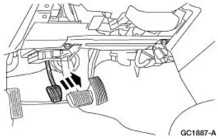
3. Lift the clutch pedal (7519) to its most upward position.
4. Remove the front seat. For additional information, refer to Section.
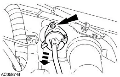
5. Unhook the clutch release lever cable (7K553) from the clutch pedal adjuster quadrant (7L583).
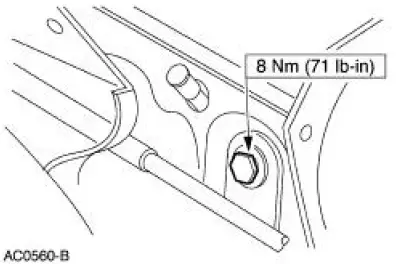
6. Open the hood, remove the screws and the clutch release cable (7K553).
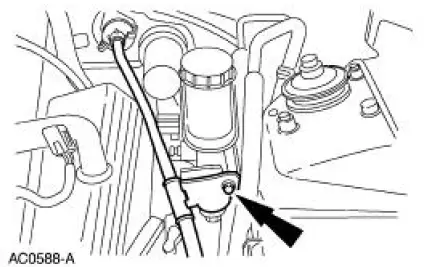
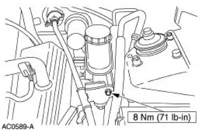
7. NOTE: On 4.6L vehicles only Remove the bolt and the clutch release lever cable bracket from the brake master cylinder (2140).
8. Raise the vehicle. For additional information, refer to Section.
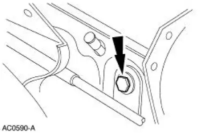
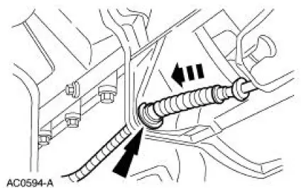
9. Remove the screw from the clutch release lever cable clamp.
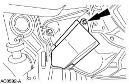
10. Remove the screw and the dust shield.
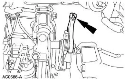
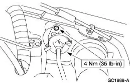
11. Pull the clutch release lever cable (7K553) and remove from the clutch release lever (7515).
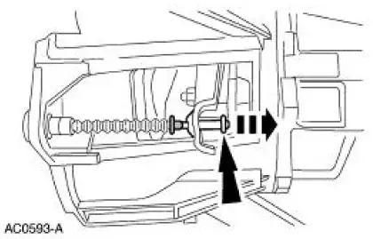
12. Remove the C-clip from the clutch release lever cable and remove the clutch release lever cable from the vehicle.
Installation
1. To install, reverse the removal procedure.
 Clutch Pedal - Quadrant and Pawl Assembly
Removal
1. Disconnect the battery ground cable (14301).
2. Loosen the nut from inside the engine compartment.
3. Loosen the nuts from inside the vehicle.
4. Loosen the screw.
5. Disconnect t ...
 Manual Transaxle/Transmission - T5OD
General Specifications
Torque Specifications
...
Other materials:
Exhaust Manifold RH
Special Tool(s)
Lifting Bracket, Engine
303-D088 (D93P-6001-A2)
Support Bar, Engine
303-290-A
Removal and Installation
1. Install the special tool.
2. Install the special tools.
3. Raise and support the vehicle. For additional ...
Rear Bumper
Removal and Installation
All vehicles
1. Remove the rear bumper cover. For additional information, refer to Rear
Bumper Cover in this
section.
2. Remove the rear bumper cover isolator.
Vehicles with 4.6L engines
3. Remove the bolts and the exhaust outlet pip ...
Cylinder Heads (Removal)
Special Tool(s)
Remover, Crankshaft Vibration
Damper
303-009 (T58P-6316-D)
Remover, Crankshaft Front Oil
Seal
303-107 (T74P-6700-A)
Engine Lift Bracket Set
303-DS086 (D93P-6001-A)
Compressor, Valve Sprin ...
