Ford Mustang (1999-2004) Service Manual: Installation
All axles
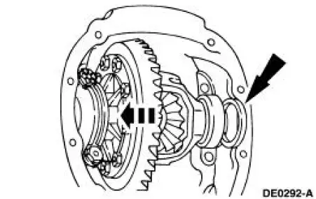
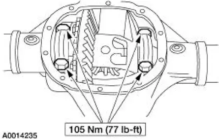
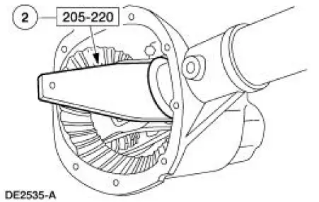
1. Position the ring gear and the differential case. Align the bolt holes by starting two bolts through the holes in the differential case and the ring gear. Press the ring gear on the differential case.
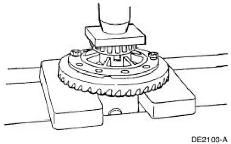
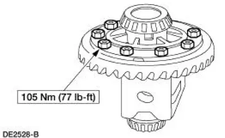
2. Install the bolts.
- Apply Stud and Bearing Mount EOAZ-19554-BA or equivalent meeting Ford specification WSK-M2G349-A1 to the bolt threads.
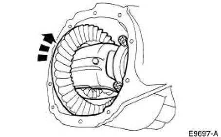
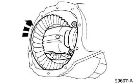
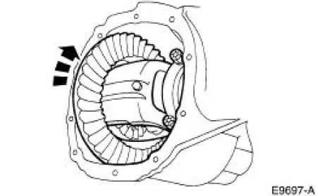
3. With the pinion depth set and the pinion installed, place the differential assembly in the differential housing.
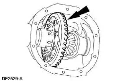
4. Install a differential bearing shim on the left side.

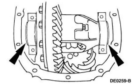
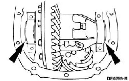
5. CAUTION: Always install the bearing caps in their identical locations and positions.
NOTE: Apply pressure toward the left side to make sure the left differential bearing cup seats correctly.
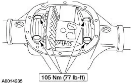
Install the left bearing cap and loosely install the bolts.
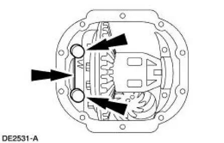
6. Install progressively larger differential bearing shims on the right side until the largest shim selected is installed by hand.
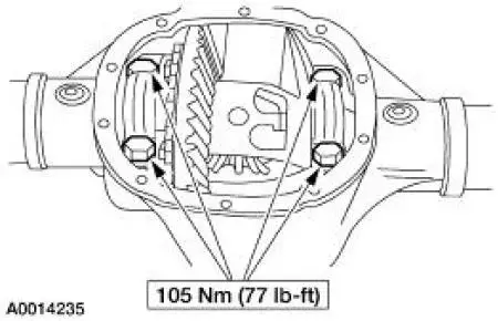
7. Install the right side bearing cap and tighten the left side and right side bolts to specification.

8. Rotate the differential assembly several times to verify that the differential bearings have seated correctly.
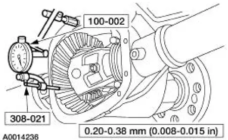
Measuring backlash
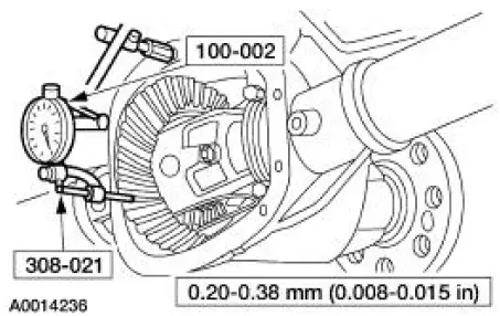
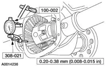
9. Using the special tools, measure the ring gear backlash.
- If backlash is within the specification, refer to Backlash within specification in this procedure. The specification shown is the full allowable range. For the preferred range, refer to Specifications in this section.
- If a zero backlash condition occurs, refer to Zero backlash in this procedure.
- If backlash is not within the specification, refer to Backlash not within specification in this procedure.

Zero backlash
10. If a zero backlash condition occurs, remove the bearing caps and add 0.51 mm (0.020 inch) to the RH side and subtract 0.51 mm (0.020 inch) from the LH side to allow backlash indication.
11. Install the bearing caps and the bolts.
12. Rotate the differential assembly several times to verify that the differential bearings have seated correctly.
13. Measure the backlash. Refer to Measuring backlash in this procedure.
Backlash not within specification
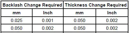
14. To increase or decrease the backlash, remove the bearing caps and install a thicker shim and thinner shim accordingly.
- If backlash is not within the specification, increase the thickness of one differential bearing shim and decrease the thickness of the other differential bearing shim by the same amount.
15. Install the bearing caps and the bolts.
16. Rotate the differential several times to verify that the differential bearings have seated correctly.
17. Using the special tools, recheck the backlash.
- If backlash is within the specification, go to Backlash within specification in this procedure. If backlash is not within the specification, repeat Backlash not within specification in this procedure.
- The specification shown is the full allowable range. For the preferred range, refer to Specifications in this section.
Backlash within specification
18. Remove the bolts and bearing caps.
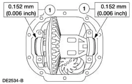
19. Set the differential bearing preload.
1. To establish differential bearing preload, increase both left and right differential bearing shim sizes by the specification shown.
2. Using the special tool, fully seat the differential bearing shims. Make sure the assembly rotates freely.
20. Install the bearing caps and bolts.
21. Using the special tools, recheck the backlash.
- The specification shown is the full allowable range. For the preferred range, refer to Specifications in this section.
22. Install the axle shafts. For additional information, refer to Axle Shaft in this section.
23. Install the differential housing cover and refill the rear axle with specified lubricant. For additional information, refer to Differential Housing Cover in this section.
24. Lower the vehicle.
 Removal
1. Remove the differential housing cover (4033) and drain the rear axle
(4001). For additional
information, refer to Differential Housing Cover in this section.
2. CAUTION: Reinstall the differentia ...
 Axle Housing
Removal and Installation
1. CAUTION: The vehicle must be on level ground and at curb height.
Mark the rear shock absorbers relative to their protective sleeve.
During installation, raise the ...
Other materials:
Stabilizer Bar
Removal
CAUTION: Suspension fasteners are critical parts because they affect
performance of vital
components and systems and their failure can result in major service expense. A
new part with
the same part number must be installed if installation becomes nec ...
Exhaust Manifold RH
Removal and Installation
1. Disconnect the battery negative cable. For additional information,
refer to Section.
2. Remove the air cleaner outlet pipe. For additional information, refer to
Section.
3. Disconnect the differential pressure feedback exha ...
Fluid Pan, Gasket and Filter
Material
Item
Specification
MERCON V Automatic
Transmission Fluid
XT-5-QM, XT-5-DM
MERCON V
1. Normal maintenance requires periodic automatic transmission fluid changes.
If a major repair,
such as a clutch, band, bearing, etc., is requir ...
