Ford Mustang (1999-2004) Service Manual: Pinpoint Test P: No Communication With The Restraints Control Module
Normal Operation
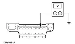
The RCM communicates with the scan tool using ISO 9141 communication mode through the data link connector (DLC).
Possible Causes
A no communication condition can be caused by:
- damage to circuit 70 (LB/WH).
- a damaged DLC.
- a damaged scan tool.
- an RCM internal concern.
PINPOINT TEST P: NO COMMUNICATION WITH THE RESTRAINTS CONTROL MODULE
| Test Step | Result / Action to Take |
| P1 CHECK THE RCM CONNECTOR C2041 AND CONNECTOR PIN 5 FOR DAMAGE | Yes GO to P2 . No REPAIR RCM C2041 or RCM C2041 pin 5 as necessary. REACTIVATE the system. |
| WARNING: If the supplemental restraint system
(SRS) is
being serviced, the system must be deactivated and restraint
system diagnostic tools must be installed. Refer to Air Bag
Supplemental Restraint System (SRS) in this section. The air bag restraint system diagnostic tools must be removed and the air bag modules reconnected when the system is reactivated to avoid non-deployment in a collision, resulting in possible personal injury. NOTE: Diagnostics or repairs are not to be performed on a seat equipped with a seat side air bag with the seat in the vehicle. Prior to attempting to diagnose or repair a seat concern when equipped with a seat side air bag, the seat must be removed from the vehicle and the restraint system diagnostic tools must be installed in the seat side air bag electrical connectors. The restraint system diagnostic tools must be removed prior to operating the vehicle over the road. NOTE: After diagnosing or repairing an SRS, the restraint system diagnostic tools must be removed before operating the vehicle over the road. NOTE: After diagnosing or repairing a seat system, the restraint system diagnostic tools must be removed before operating the vehicle over the road. NOTE: The SRS must be fully operational and free of faults before releasing the vehicle to the customer.
|
|
| P2 CHECK THE DLC CONNECTOR C251 AND CONNECTOR PIN 7 FOR DAMAGE | Yes GO to P3 . No REPAIR DLC C251 or DLC C251 pin 7 as necessary. RETEST the communication to RCM. RECONNECT the system. REACTIVATE the system. PROVE OUT the system. REFER to Air Bag Supplemental Restraint System (SRS) in this section. |
|
|
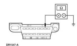
| P3 CHECK CIRCUIT 70 (LB/WH) FOR SHORT TO BATTERY | Yes REPAIR the battery short. RETEST the communication to RCM. RECONNECT the system. REACTIVATE the system. PROVE OUT the system. REFER to Air Bag Supplemental Restraint System (SRS) in this section. No GO to P4 |
|
|
| P4 CHECK CIRCUIT 70 (LB/WH) FOR SHORT TO GROUND | Yes REPAIR the circuit. RETEST the communication to RCM. RECONNECT the system. REACTIVATE the system. PROVE OUT the system. REFER to Air Bag Supplemental Restraint System (SRS) in this section. No GO to P5 |
|
|
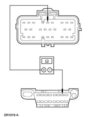
| P5 CHECK CIRCUIT 70 (LB/WH) FOR AN OPEN | Yes INSTALL a new RCM. RETEST the communication to RCM. RECONNECT the system. REACTIVATE the system. PROVE OUT the system. REFER to Air Bag Supplemental Restraint System (SRS) in this section. No REPAIR the circuit. RETEST the communication to RCM. RECONNECT the system. REACTIVATE the system. PROVE OUT the system. REFER to Air Bag Supplemental Restraint System (SRS) in this section. |
|
 Pinpoint Test O: DTC B1870 - Air Bag Indicator Shorted to Battery
Normal Operation
The air bag indicator is designed to illuminate for 6 (+/-2) seconds
when the ignition switch is turned to
the RUN position. This initial 6 seconds of illumination is considere ...
 Inspection and Repair After a Supplemental Restraint
System (SRS) Deployment
Inspection and Repair After a Supplemental Restraint
System (SRS) Deployment
WARNING: If the supplemental restraint system (SRS) is being serviced,
the system must
be deactivated and restraint system diagnostic tools must be installed. Refer to
Air Bag
Supplemental Restraint ...
Other materials:
Clutch Pedal - Quadrant and Pawl Assembly
Removal
1. Disconnect the battery ground cable (14301).
2. Loosen the nut from inside the engine compartment.
3. Loosen the nuts from inside the vehicle.
4. Loosen the screw.
5. Disconnect the brake pedal position (BPP) switch electrical connector.
...
Differential Case
Special Tool(s)
2-Jaw Puller
205-D072 (D97L-4221-A) or
equivalent
Dial Indicator Gauge with
Holding Fixture
100-002 (TOOL-4201-C) or
equivalent
Gauge, Clutch Housing
308-021 (T75L-4201-A) or
equivalent
Instal ...
Exhaust Manifold LH
Special Tool(s)
Lifting Bracket, Engine
303-D088 (D93P-6001-A2)
Support Bar, Engine
303-290-A
Removal and Installation
1. Install the special tool.
2. Install the special tools.
3. Raise and support the vehicle. For additional ...
