Ford Mustang (1999-2004) Service Manual: Removal
1. Raise and support the vehicle.
2. Remove the rear wheel and tire assemblies.
3. CAUTION: Remove the rear brake calipers to prevent drag during the drive pinion bearing preload adjustment.
CAUTION: Do not allow the calipers to hang from the brake hoses.
Remove the rear brake caliper and support bracket from the knuckle as an assembly. Wire the caliper and support bracket assembly out of the way.
4. CAUTION: Index-mark the driveshaft flange and rear axle pinion flange (4851) to maintain initial balance during installation.
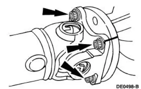
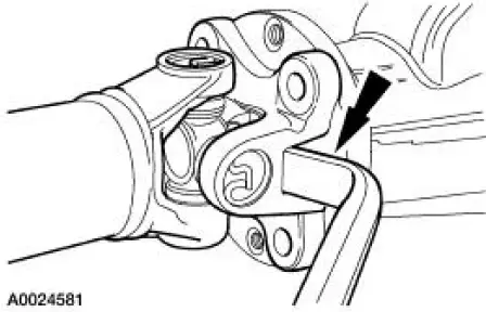
CAUTION: The driveshaft centering socket yoke fits tightly on the rear axle pinion flange pilot. Never hammer on the driveshaft (4602) or any of its components to disconnect the yoke from the flange. Pry only in the area shown, with a suitable tool, to disconnect the yoke from the flange.
Disconnect and position the driveshaft out of the way.
5. Install an Nm (inch/pound) torque wrench on the nut and record the torque necessary to maintain rotation of the drive pinion gear through several revolutions.
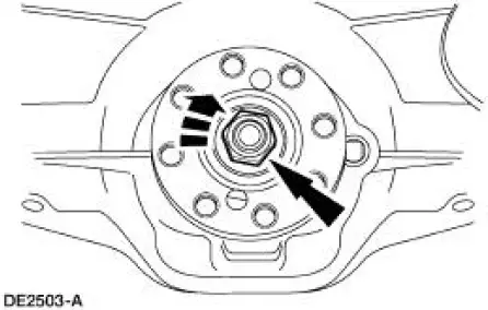
6. CAUTION: After removing the nut, discard it. Use a new nut for installation.
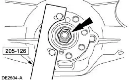
Use the special tool to hold the rear axle pinion flange while removing the nut.
7. Index-mark the rear axle pinion flange and drive pinion gear stem to maintain initial balance during installation.
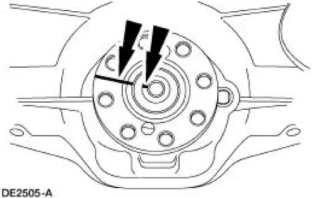
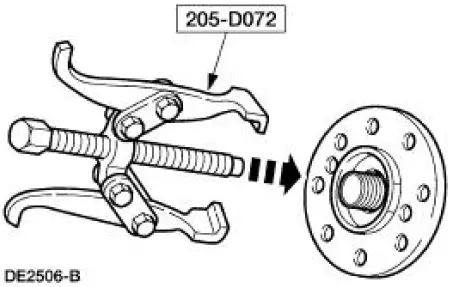
8. Using the special tool, remove the rear axle pinion flange.
 Drive Pinion Flange
Special Tool(s)
2-Jaw Puller
205-D072 (D97L-4221-A) or
equivalent
Holding Fixture, Drive Pinion
Flange
205-126 (T78P-4851-A)
Installer, Drive Pinion Flange
205-002 ...
 Installation
1. Inspect the rear axle pinion flange seal journal for rust, nicks, and
scratches prior to installing
the flange. Polish the seal journal with fine crocus cloth, if necessary.
2. Lubricate the rear ...
Other materials:
Selector Lever
Removal
1. Remove the shifter top control panel.
2. Disconnect the electrical connectors.
3. Remove the shifter bezel.
4. Remove the bulb from the bezel.
5. Disconnect the TCS connector.
6. CAUTION: Extra force may be needed to lift up on the handl ...
Auxiliary input jack
WARNING: Driving while distracted can result in loss of vehicle
control, crash and injury. We strongly recommend that you use
extreme caution when using any device that may take your focus off
the road. Your primary responsibility is the safe operation of your ...
Body System (Diagnosis and Testing)
Inspection and Verification
Leaks
NOTE: Trim will reveal the location of most leaks.
1. Remove any trim or carpet in the general area of the leak.
2. Road test or water test the vehicle.
3. Inspect for a dust pattern around the area in question. In ...
