Ford Mustang (1999-2004) Service Manual: Removal
1. Disconnect the battery ground cable. For additional information, refer to Section.
2. Remove the engine air cleaner outlet pipe. For additional information, refer to Section.
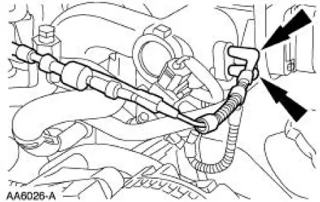
3. Disconnect the vacuum hose and the idle air control (IAC) valve electrical connector.
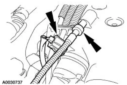
4. Disconnect the throttle position (TP) sensor electrical connector and the evaporative emissions (EVAP) return tube.
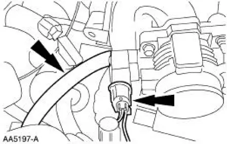
5. Disconnect the accelerator and the speed control cables from the throttle body cam.
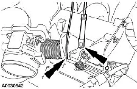
6. Remove the bolts and position the accelerator cable bracket assembly aside.
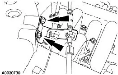
7. Disconnect the differential pressure feedback exhaust gas recirculation (EGR) system electrical and vacuum connections.
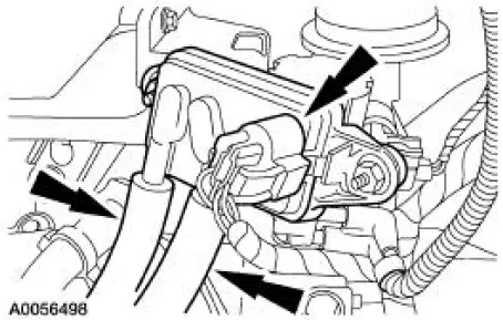
8. Disconnect the EGR vacuum regulator solenoid electrical and vacuum connections.
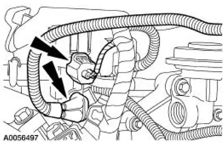
9. Disconnect the positive crankcase ventilation (PCV) tube.
10. Disconnect the vacuum hoses.
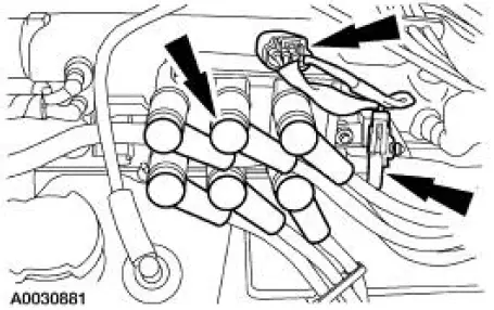
11. Disconnect the following:
- Ignition coil electrical connector.
- Radio interference capacitor electrical connector.
- Spark plug wires.
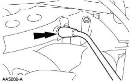
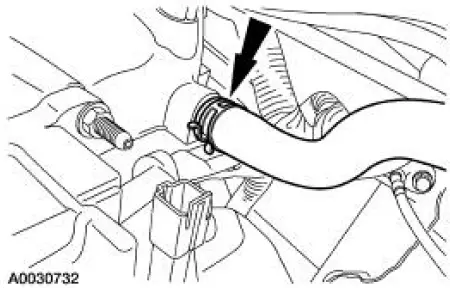
12. Disconnect the vacuum hose.
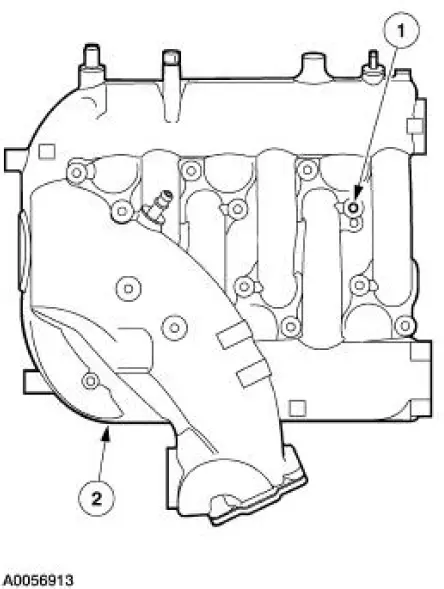
13. NOTE: For ease in installation, record the location of the long bolts and the short bolts.
Remove the upper intake manifold.
1. Remove the 12 bolts.
2. Remove the upper intake manifold.
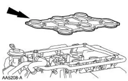
14. Remove and discard the upper intake manifold gasket.

 Installation
1. Install a new upper intake manifold gasket.
2. NOTE: Refer to the location note made during removal and make sure
the bolts are installed in
the correct locations.
Install the upper intake mani ...
Other materials:
Engine (Removal)
Special Tool(s)
Special Tool(s)
Support Bracket, Engine
303-639
Spreader Bar
303-D089 (D93P-6001-A3)
Lifting Bracket Set, Engine
303-D074 (D91P-6001-A)
Removal
1. Remove the hood.
2. Remove the battery. For additi ...
Principles of Operation
There are four main principles involved with the basic theory of
operation:
heat transfer
latent heat of vaporization
relative humidity
effects of pressure
Heat Transfer
If two substances of different temperature are placed near each other,
t ...
Temperature and Manifold Absolute Pressure (T-MAP)
Sensor - Cobra
Removal and Installation
1. Disconnect the temperature manifold absolute pressure (T-MAP)
sensor electrical connector.
2. Remove the bolts and the T-MAP sensor.
3. To install, reverse the removal procedure. ...
