Ford Mustang (1999-2004) Service Manual: Air Conditioning (Description and Operation)
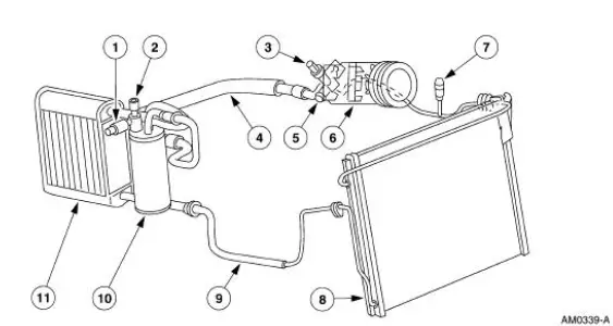
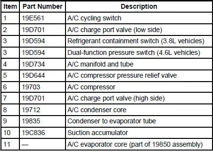
The A/C refrigerant system is a clutch cycling orifice tube type. The system components are:
- A/C compressor (19703)
- A/C clutch (2884)
- A/C condenser core (19712)
- A/C evaporator core (19860)
- suction accumulator (19C836)
- connecting refrigerant lines
The refrigeration system operation is controlled by the:
- A/C evaporator core orifice (19D990).
- A/C cycling switch (19E561).
- A/C compressor pressure relief valve (19D644).
- Refrigerant containment switch (3.8L) (19D594).
- Dual-function pressure switch (4.6L) (19D594).
The refrigerant system incorporates an A/C compressor controlled by an A/C cycling switch.
The A/C cycling switch senses A/C evaporator core pressure to control A/C compressor operation.
An A/C compressor pressure relief valve is installed in the A/C manifold and tube (19D734) to protect the refrigerant system against excessively high refrigerant pressures.
An evaporator core orifice is installed in the A/C evaporator core inlet tube to meter the liquid refrigerant into the A/C evaporator core.
A refrigerant containment switch is installed on 3.8L vehicles to cut-off A/C compressor operation in the event of abnormally high refrigerant system pressure.
A dual-function pressure switch is used on 4.6L vehicles for cooling fan control, and to cut-off A/C compressor operation in the event of abnormally high refrigerant system pressure.
Refrigeration System Components
- A/C Compressor and Clutch Assembly
- A/C Compressor Pressure Relief Valve
- Refrigerant Lines
- Evaporator Core Orifice
- Suction Accumulator
- Dual-Function Pressure Switch (4.6L)
- Spring Lock Coupling
 Air Conditioning
General Specifications
Torque Specifications
...
 A/C Compressor and Clutch Assembly
NOTE: Internal A/C compressor components are not serviced separately.
The FS-10 A/C compressor
is serviced only as an assembly. The A/C clutch pulley, A/C clutch field coil
(19D798) and the shaft
...
Other materials:
Installation
WARNING: To reduce the risk of serious personal injury, read
and follow all warnings,
cautions and notes at the beginning of the removal procedure.
1. Install the passenger air bag module.
1. Position the passenger air bag module into the instrume ...
Manual
WARNING: Brake fluid contains polyglycol ethers and polyglycols.
Avoid contact with
eyes. Wash hands thoroughly after handling. If brake fluid contacts
eyes, flush eyes with
running water for 15 minutes. Get medical attention if irritation
persist ...
External Controls (Diagnosis and Testing)
Refer to Wiring Diagrams Cell 37 , Shift Lock for schematic and connector
information.
Refer to Wiring Diagrams Cell 29 , Transmission Control for schematic and
connector information.
Special Tool(s)
73 Digital Multimeter
105-R0051 or equivalent ...
