Ford Mustang (1999-2004) Service Manual: Air Conditioning (Description and Operation)
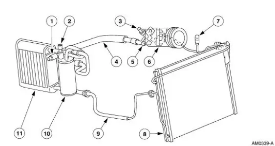
The A/C refrigerant system is a clutch cycling orifice tube type. The system components are:
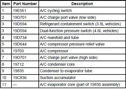
- A/C compressor (19703)
- A/C clutch (2884)
- A/C condenser core (19712)
- A/C evaporator core (19860)
- suction accumulator (19C836)
- connecting refrigerant lines
The refrigeration system operation is controlled by the:
- A/C evaporator core orifice (19D990).
- A/C cycling switch (19E561).
- A/C compressor pressure relief valve (19D644).
- Refrigerant containment switch (3.8L) (19D594).
- Dual-function pressure switch (4.6L) (19D594).
The refrigerant system incorporates an A/C compressor controlled by an A/C cycling switch.
The A/C cycling switch senses A/C evaporator core pressure to control A/C compressor operation.
An A/C compressor pressure relief valve is installed in the A/C manifold and tube (19D734) to protect the refrigerant system against excessively high refrigerant pressures.
An evaporator core orifice is installed in the A/C evaporator core inlet tube to meter the liquid refrigerant into the A/C evaporator core.
A refrigerant containment switch is installed on 3.8L vehicles to cut-off A/C compressor operation in the event of abnormally high refrigerant system pressure.
A dual-function pressure switch is used on 4.6L vehicles for cooling fan control, and to cut-off A/C compressor operation in the event of abnormally high refrigerant system pressure.
Refrigeration System Components
- A/C Compressor and Clutch Assembly
- A/C Compressor Pressure Relief Valve
- Refrigerant Lines
- Evaporator Core Orifice
- Suction Accumulator
- Dual-Function Pressure Switch (4.6L)
- Spring Lock Coupling
 Air Conditioning
General Specifications
Torque Specifications
...
 A/C Compressor and Clutch Assembly
NOTE: Internal A/C compressor components are not serviced separately.
The FS-10 A/C compressor
is serviced only as an assembly. The A/C clutch pulley, A/C clutch field coil
(19D798) and the shaft
...
Other materials:
Air Conditioning (A/C) Pressure Relief Valve - 4.6L
Material
Item
Specification
PAG Refrigerant Compressor
Oil (R-134a Systems)
F7AZ-19589-DA (Motorcraft YN-
12-C)
WSH-M1C231-
B
Removal and Installation
NOTE: Installation of a new suction accumulator is not required when
repairing the ...
General Information
INTRODUCTION
In the past, when cars were simpler, diagrams were simpler. All components
were connected by wires, and
diagrams seldom exceeded 4 pages in length. Today, some wiring diagrams require
more than 16 pages. It
would be impractical to expect a servi ...
Cabin air filter
Note: Make sure you have a cabin air filter installed at all times.
This
prevents foreign objects from entering the system. Running the system
without a filter in place could result in degradation or damage to the
system.
Your vehicle is equipped with a cabi ...
