Ford Mustang (1999-2004) Service Manual: Catalyst Monitor Sensor
Special Tool(s)
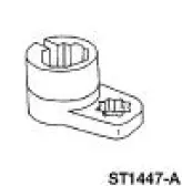 |
Socket, Exhaust Gas Oxygen Sensor 303-476 (T94P-9472-A) |
Material
| Item | Specification |
| Penetrating and Lock Lubricant or equivalent | E8AZ-19A501- B |
Removal and Installation
1. Disconnect the battery ground cable. For additional information, refer to Section.
2. Raise and support the vehicle. For additional information, refer to Section.
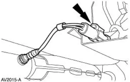
3. NOTE: Two catalyst monitor sensors are used for the engine control system. They are located in the dual converter Y pipe downstream from the catalyst. The left side catalyst monitor sensor is shown, the right side is similar.
Disconnect the connector.
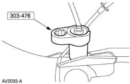
4. NOTE: If necessary, lubricate the sensors with penetrating and lock lubricant to assist in removal.
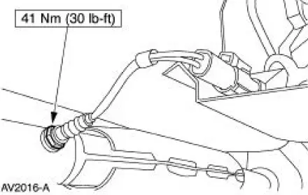
Using the special tool, remove the catalyst monitor sensors from the dual converter Y pipe.
5. To install, reverse the removal procedure.
 Heated Oxygen Sensor (HO2S)
Special Tool(s)
Socket, Exhaust Gas Oxygen
Sensor
303-476 (T94P-9472-A)
Material
Item
Specification
Penetrating and Lock Lubricant
or equivalent
E8AZ-19A501-
B
...
 Clutch Pedal Position (CPP) Switch
Removal
1. Disconnect the battery ground cable. For additional information,
refer to Section.
2. Disconnect the connector.
3. Remove the bolt and the clutch pedal position (CPP) switch.
In ...
Other materials:
Road Test
Verify the customer concern by carrying out a road test on a smooth road. If
any vibrations are
apparent.
To maximize tire performance, inspect for signs of incorrect inflation and
uneven wear, which may
indicate a need for balancing, rotation, or front susp ...
Getting the services you need
Warranty repairs to your vehicle must be performed by an authorized
dealer. While any authorized dealer handling your vehicle line will
provide warranty service, we recommend you return to your selling
authorized dealer who wants to ensure your continued satis ...
Removal
NOTE: This procedure applies to both the LH and RH halfshafts.
1. CAUTION: The vehicle must be on level ground and at curb height.
Mark the rear shock absorber relative to the protective sleeve.
During installation, raise the suspension to this reference ...
