Ford Mustang (1999-2004) Service Manual: Assembly
1. Carry out the following before reassembling:
- Inspect the gears for broken or cracked teeth. Check for unusual wear patterns.
- Inspect the thrust washers for face wear, cracks, scoring and for signs of heat damage.
- Inspect the bearings, bearing cups and the synchronizers for wear or damage.
- Inspect the output shaft for scoring or worn or damaged splines. Install new components as necessary.
2. Lubricate all components with the recommended transmission fluid when reassembling.
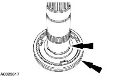
3. NOTE: Position the output shaft with the output end facing upward.
NOTE: Install the synchronizer assembly with the deeper center flange of the synchronizer hub facing toward the rear of the output shaft.
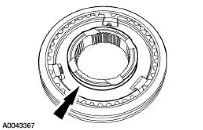
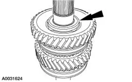
Install the first/second synchronizer assembly on the output shaft, then install a new retaining ring.
- It may be necessary to press the hub into position on the shaft.
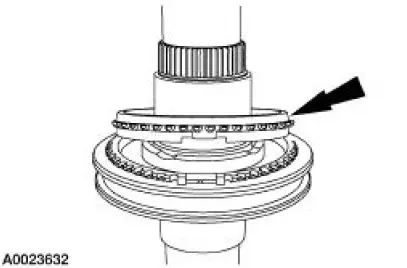
4. Install the first gear synchronizer blocking ring.
- Align the blocking ring tabs with the synchronizer assembly.
5. Install the outer first gear synchronizer cone.
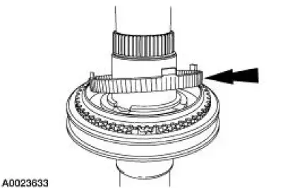
6. Install the inner first gear synchronizer cone. Rotate the inner cone till it is seated.
7. Install the first gear needle bearing.
- Apply petroleum jelly to the bearing.
8. Install first gear.
- Rotate the gear to align the gear slots with the inner cone tabs.
9. Install the reverse synchronizer cone.
10. Install the reverse gear blocking ring.
11. Using the special tools, install the reverse gear bearing spacer.
12. Install reverse gear needle bearing.
- Apply petroleum jelly to the bearing.
13. Install reverse gear.
- Rotate the gear to align the gear slots with the inner cone tabs.
14. Install the check ball.
- Use petroleum jelly to hold the check ball in place.
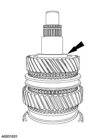
15. Install the thrust washer. Be sure to align the slot in the washer with the check ball.
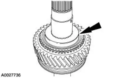
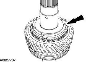
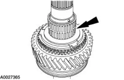
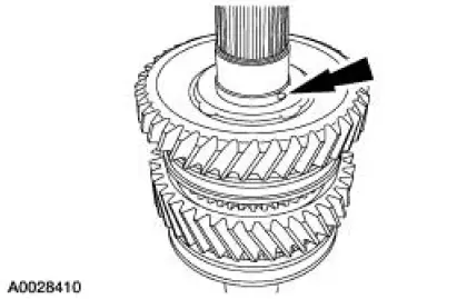
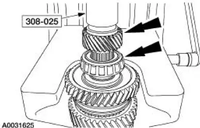
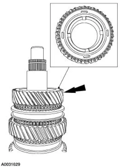
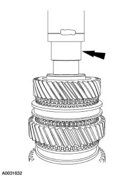
16. Install a new rear output shaft bearing, then fifth gear. Using the special tool, press both the bearing and gear into place.
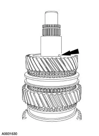
17. Reposition the output shaft with the input end facing upward.
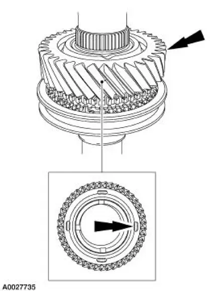
18. Install the second gear synchronizer blocking ring. Rotate the blocking ring until seated.
19. Install the second gear synchronizer outer cone and the second gear synchronizer inner cone.
20. Install the second gear bearing.
- Apply petroleum jelly to the bearing.
21. Install second gear.
- Rotate the gear to align the gear slots with the inner cone tabs.
22. Install the check ball.
- Use petroleum jelly to hold the check ball in place.
23. Install the thrust washer. Be sure to align the slot in the washer with the check ball.
24. Press the bearing spacer onto the output shaft.
25. Install the third gear bearing.
- Apply petroleum jelly to the bearing.
26. Install third gear.
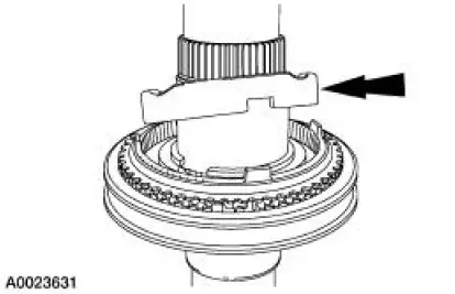
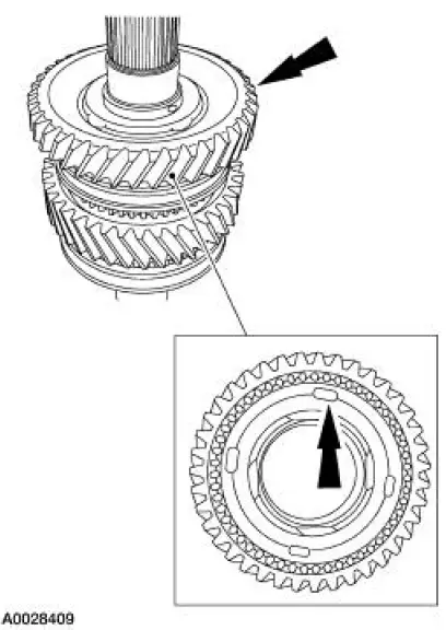
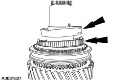
27. Install the third gear synchronizer blocking ring.
28. Install the third/fourth gear synchronizer body.
- Install the synchronizer body with the raised center facing downward.
- Rotate the blocking ring until seated.
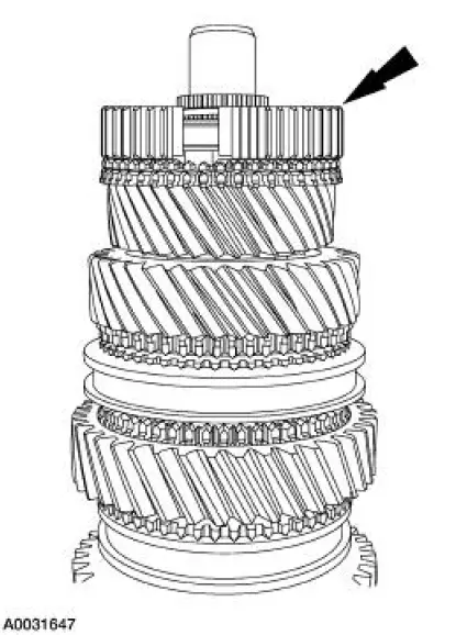
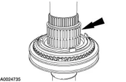
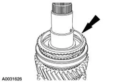
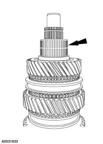
29. Install a new retaining ring.
 Disassembly
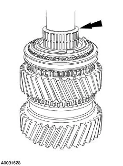
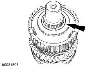
1. Remove the retaining ring above fifth gear.
2. CAUTION: Hand tighten the special tool to prevent gear damage.
CAUTION: Support the output shaft while using the press to prevent
damage to the
sha ...
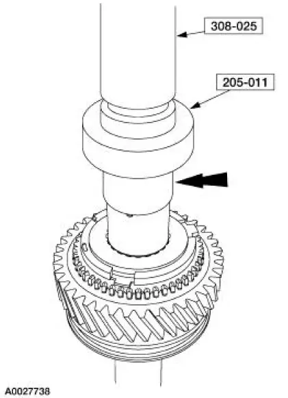
 Countershaft Bearing
Special Tool(s)
Remover, Drive Pinion Bearing
Cone
205-D002 (D79L-4621-A) or
equivalent
Installer, Drive Pinion Bearing
Cone
205-011 (T57L-4621-B)
Disassembly and A ...
Other materials:
Torque Converter Turbine to Pump Stator Interference
Check
1. NOTE: Front pump support may remain in front pump support and gear
during this test.
Position the torque converter with the pump drive up.
2. Install the front pump support to engage the mating splines of the front
pump support shaft on
the torque convert ...
Creating a MyKey
Use the information display to create a MyKey.
For Type 1 information displays:
1. Insert the key you want to program into the ignition.
2. Switch the ignition on.
3. Access the main menu within the information display, and press
SETUP using the information d ...
Water Pump - 3.8L
Material
Item
Specification
Motorcraft Premium Gold
Engine Coolant
VC-7-A (in Oregon VC-7-B)
(yellow color)
WSS-M97B51-
A1
Removal and Installation
1. Drain the engine coolant. For additional information, refer to Cooling
System Dra ...
