Ford Mustang (1999-2004) Service Manual: Brake System (Diagnosis and Testing)
Refer to Wiring Diagrams Cell 60, Instrument Cluster for schematic and connector information.
Refer to Wiring Diagrams Cell 97, Daytime Running Lamps for schematic and connector information.
Special Tool(s)
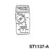 |
73 Digital Multimeter 105-R0051 or Equivalent |
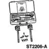 |
ABS Brake and Pressure Test Kit 107-02350 or Equivalent |
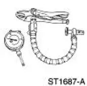 |
Tire and Wheel Runout Gauge Set 134-00199 or Equivalent |
- Inspection and Verification
- Vibration When Brakes are Applied
- Symptom Chart
- Pinpoint Tests
- Component Tests
 Brake System (Description and Operation)
Component Locations
+
The vehicle is equipped with a vacuum-assisted or a hydro-boost power braking
system.
The braking system is a front-to-rear split hydraulic system.
The front wheel b ...
 Inspection and Verification
WARNING: Use of any other than the approved DOT 3 brake fluid will
cause permanent
damage to brake components and will render the brakes inoperative.
WARNING: Brake fluid contains polyglycol ethers ...
Other materials:
Valve Spring Strength
Special Tool(s)
Pressure Gauge, Valve/Clutch
Spring
303-006 (TOOL-6513-DD) or
equivalent
1. Use a Valve/Clutch Spring Pressure Gauge to check the valve spring for
correct strength at the
specified valve spring length.
Refer to the appr ...
Diagnostic Instructions - Air Bag Supplemental Restraint
System (SRS)
Special Tool(s)
Worldwide Diagnostic System
(WDS)
418-F224,
New Generation STAR (NGS)
Tester
418-F052, or equivalent scan
tool
The symptom chart can be used to help locate the air bag supplemental
restraint system (SRS)
concerns if n ...
Idle Air Control (IAC) Valve - Mach I
Removal and Installation
1. Remove the air intake scoop. For additional
information, refer to Section.
2. Disconnect the idle air control (IAC) valve electrical connector.
3. Remove the bolts, the IAC valve and the gasket.
4. NOTE: Install a new ga ...
