Ford Mustang (1999-2004) Service Manual: Drive Pinion Flange and Drive Pinion Seal
Special Tool(s)
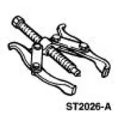 |
2-Jaw Puller 205-D072 (D97L-4221-A) or equivalent |
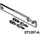 |
Holding Fixture, Drive Pinion Flange 205-126 (T78P-4851-A) |
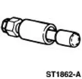 |
Installer, Drive Pinion Flange 205-002 (TOOL-4858-E) or equivalent |
 Removal
1. Raise and support the vehicle.
2. Remove the rear wheel and tire assemblies.
3. CAUTION: Remove the rear brake calipers to prevent drag during the
drive pinion
bearing preload adjustment.
CAU ...
Other materials:
Gearshift Lever and Boot
Material
Removal and Installation
1. Remove the gearshift lever knob.
2. Remove the console panel gearshift plate. Lift the gearshift lever boot
over the gearshift lever.
3. Remove the bolts and the shift lever.
4. Remove the screws and the inner shif ...
Installation
1. CAUTION: To prevent refrigerant system contamination, do not allow
dirt or other
foreign materials to enter the A/C compressor.
Clean the A/C compressor nose area.
2. Place the shaft seal on the special tool. Lubricate the shaft seal and the
special tool ...
Timing Chain
Removal
1. Remove the timing cover. For additional information, refer to Engine
Front Cover in this section.
2. Remove the camshaft position sensor drive gear.
1. Remove the bolt.
2. Remove the camshaft position sensor drive gear.
3. Rotate the ...
