Ford Mustang (1999-2004) Service Manual: Connecting Rod - Twist
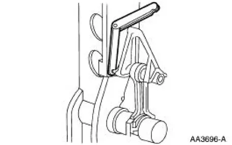
1. Measure the connecting rod twist on a suitable alignment fixture. Follow the instructions of the fixture manufacturer. Verify the measurement is within specification.
- Refer to the appropriate section in Group for the procedure.
- If out of specification, install new components as necessary. Refer to the appropriate section in Group for the procedure.
Connecting Rod -Piston Pin Side Clearance
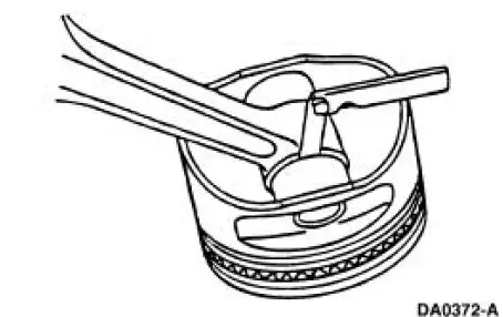
1. Measure the clearance between the connecting rod and the piston. Verify the measurement is within specification.
- Refer to the appropriate section in Group for the procedure.
- If out of specification, install new components as necessary. Refer to the appropriate section in Group 303 for the procedure.
 Connecting Rod - Bushing Diameter
1. Measure the inner diameter of the connecting rod bushing, if equipped.
Verify the diameter is
within specification.
Refer to the appropriate section in Group for the procedure.
If out of s ...
 Connecting Rod - Bearing Journal Clearance
Special Tool(s)
Plastigage
303-D031 (D81L-6002-B) or
equivalent
NOTE: The crankshaft connecting rod journals must be within
specifications to check the connecting
rod bearing journa ...
Other materials:
Idle Air Control (IAC) Valve - 4.6L (2V)
Removal
1. Disconnect the battery ground cable. For additional information,
refer to Section.
2. NOTE: Discard the idle air control (IAC) valve gasket.
Remove the IAC valve.
Disconnect the connector.
Disconnect the hose.
Remove the bolts, ...
Installing child seats
Child Seats
Use a child safety seat (sometimes
called an infant carrier, convertible
seat, or toddler seat) for infants,
toddlers or children weighing
40 pounds (18 kilograms) or less
(generally age four or younger).
Using Lap and Shoulder Belts
WARNING: Airb ...
Pinpoint Test I: LFC 33/DTC B1933 - Passenger Air Bag Circuit Resistance
High
Normal Operation
The restraints control module (RCM) monitors the resistance of the
passenger air bag ignitor by
measuring the resistance between pins 6 and 7. If the RCM detects high
resistance between these
pins, it will store a diagnostic trouble cod ...
