Ford Mustang (1999-2004) Service Manual: Disassembly
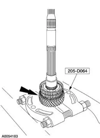
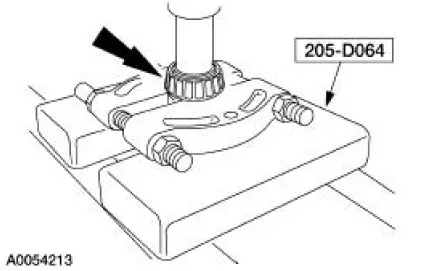
1. CAUTION: Hand tighten the special tool to prevent gear damage.
CAUTION: Support the output shaft while using the press to prevent damage to the shaft or gears.
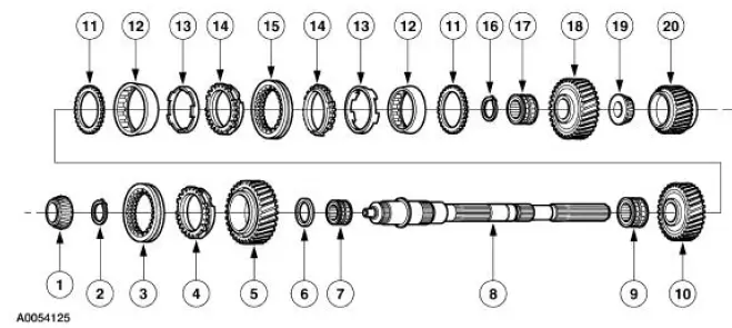
Using the special tool and a press, remove first gear, the output shaft rear bearing and the fifth driven gear.
- Discard the output shaft bearing.
- Inspect the gear for wear or damage. Install a new gear as necessary.
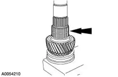
2. Remove the first gear needle bearing.
- Inspect the needle bearing for wear or damage. Install a new needle bearing as necessary.
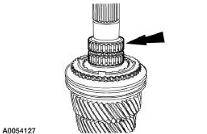
3. Remove and discard the snap ring.
4. Remove the first gear synchronizer thrust washer, the inner cone, the friction cone and the first gear synchronizer blocking ring.
- Inspect all components for wear or damage. Install new components as necessary.
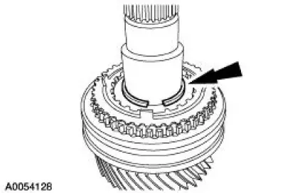
5. Remove the synchronizer spring, then remove the synchronizer sleeve.
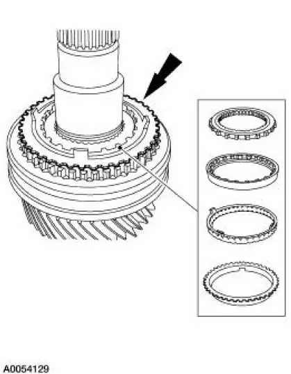
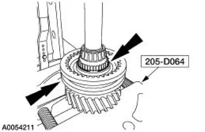
6. NOTE: Install the special tool behind second gear with the flat side of the tool facing second gear.
Using the special tool, remove the second gear, the second gear synchronizer thrust washer, the inner cone, the friction cone, the second gear synchronizer blocking ring and the synchronizer hub.
- Inspect the gear for wear or damage. Install a new gear as necessary.
- Inspect the all synchronizer components for wear or damage. Install a new components as necessary.
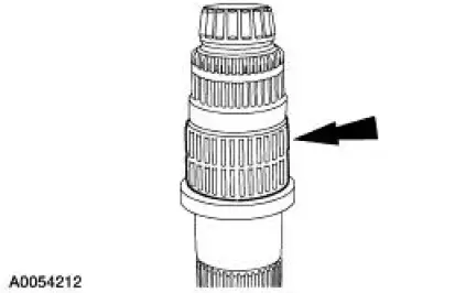
7. Remove the second gear needle bearing.
- Inspect the needle bearing for wear or damage. Install a new needle bearing as necessary.
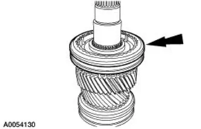
8. NOTE: Reposition the output shaft on the press with the input shaft end facing upward.
Remove and discard the snap ring, then using the special tool, remove the third/fourth gear synchronizer assembly, the third gear synchronizer blocking ring and the third gear.
- Inspect the gear for broken or cracked teeth. Install a new gear as necessary.
9. Remove the third gear needle bearing.
- Inspect the needle bearing for wear or damage. Install a new needle bearing as necessary.
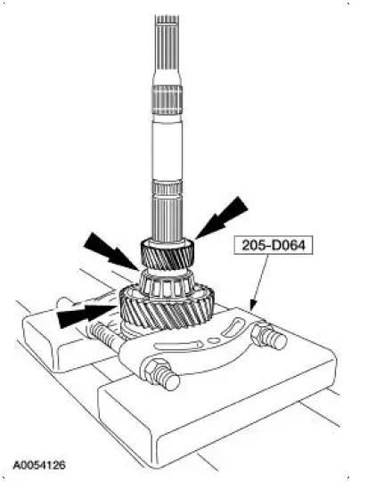
10. NOTE: Install the special tool with the flat side facing the bearing.
Using the special tool, press the output shaft front bearing from the output shaft.
11. Inspect the synchronizers.
- Check for worn, nicked or broken teeth. Install a new synchronizer as necessary.
- Check keys for wear or distortion. Install a new synchronizer as necessary.
- Check springs for distortion. Install a new synchronizer as necessary.
12. Inspect the synchronizer blocking rings.
- Check for wear or damage. Install new synchronizer blocking rings as necessary.
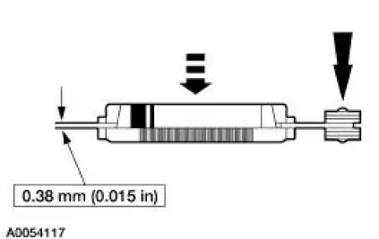
- Check the clearance between the synchronizer blocking ring and the gear.
- Position the blocking ring onto the gear. Make sure the correct blocking ring is measured with the correct gear and that the blocking ring is fully seated on the gear.
- Insert a feeler gauge and measure the clearance, while applying pressure and rotating the blocking ring. The measurement should be the same around the entire circumference. If the clearance is less than 0.38 mm (0.015 in), install new blocking rings.
13. Inspect the output shaft for scoring or worn or damaged splines. Install a new output shaft as necessary.
 Output Shaft
Special Tool(s)
Puller, Bearing
205-D064 (D84L-1123-A)
Adapter for 303-224 (Handle)
205-153 (T80T-4000-W)
Installer, Output Shaft Rear
Bearing
308-401
...
 Assembly
1. Lubricate all components with the recommended transmission fluid when
reassembling.
2. Using the special tools, press the output shaft front bearing on the output
shaft.
3. Install the third g ...
Other materials:
Clutch And Clutch Field Coil
Special Tool(s)
2-Jaw Puller
205-D026 (D80L-1002-L) or
equivalent
Installer, A/C Compressor Coil
412-065 (T89P-19623-EH)
Holding Fixture, Compressor
Clutch (3.8L vehicles)
412-098 (T94P-19703-AH)
Holding ...
Pinpoint Tests
PINPOINT TEST A: THE ENGINE DOES NOT CRANK AND THE
RELAY DOES CLICK
Test Step
Result / Action to Take
A1 CHECK THE VOLTAGE TO THE STARTER RELAY
YesGO to A2 .
No
REPAIR circuit 1050 (LG/VT) for an open. TEST the
system for normal operation. ...
Transmission fluid check
Checking Automatic Transmission Fluid
Note: Transmission fluid should be checked and, if required, added by
an authorized dealer.
The automatic transmission does not have a transmission fluid dipstick.
See your Scheduled Maintenance Information for scheduled ...
